Inspection [12/2019 - 10/2022]: Procedure
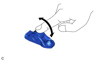
- INSPECT NO. 1 VALVE ROCKER ARM SUB-ASSEMBLY
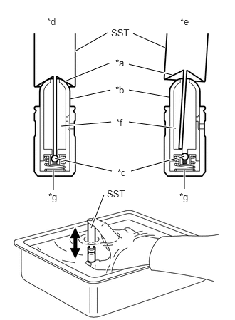
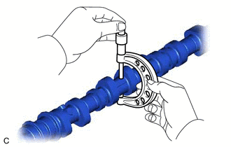
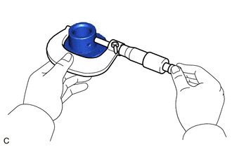
- INSPECT VALVE LASH ADJUSTER ASSEMBLY NOTE:
- Keep the valve lash adjuster assembly free from dirt and foreign matter.
- Only use clean engine oil.
- Place the valve lash adjuster assembly into a container filled with engine oil.
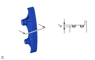
- Insert the tip of SST into the plunger and use the tip to press down on the check ball inside the plunger.
*a Tapered Path *b Plunger *c Check Ball *d Correct *e Incorrect *f Low Pressure Chamber *g High Pressure Chamber - SST: 09276-75010
- Squeeze SST and the valve lash adjuster assembly together to move the plunger up and down 5 to 6 times.
- Check the movement of the plunger and bleed any air.
OK
Plunger moves up and down.
NOTE:When bleeding the air from the high-pressure chamber, make sure that the tip of SST is pressing the check ball as shown in the illustration. If the check ball is not pressed, air will not bleed.
- After bleeding the air, remove SST. Then try to quickly and firmly press the plunger by hand.
OK
Plunger is very difficult to move.
HINT:
If the plunger is easy to move, replace the valve lash adjuster assembly.
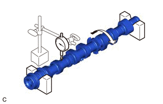
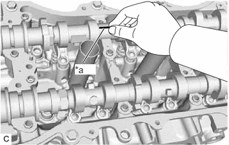
- INSPECT CAMSHAFT
- Inspect the camshaft for runout.
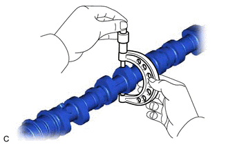
- Using a micrometer, measure the cam lobe height.
Standard Cam Lobe Height
Item Specified Condition Intake camshaft 44.335 to 44.435 mm (1.74547 to 1.74941 in.) Exhaust camshaft 43.866 to 43.966 mm (1.72701 to 1.73094 in.) Exhaust (for Fuel Pump) 40.554 to 40.654 mm (1.59661 to 1.60055 in.) Minimum Cam Lobe Height
Item Specified Condition Intake camshaft 44.235 mm (1.74154 in.) Exhaust camshaft 43.766 mm (1.72307 in.) Exhaust (for Fuel Pump) 40.454 mm (1.59268 in.) HINT:
If the cam lobe height is less than the minimum, replace the camshaft.
- Using a micrometer, measure the journal diameter.
Standard Journal Diameter
Item Specified Condition No. 1 journal 35.946 to 35.960 mm (1.41519 to 1.41575 in.) No. 2, No. 3, No. 4 journals 25.959 to 25.975 mm (1.02201 to 1.02264 in.) No. 5 journal 25.969 to 25.985 mm (1.02240 to 1.02303 in.) HINT:
If the journal diameter is not as specified, check the oil clearance.
See step 17
- INSPECT CYLINDER HEAD SET BOLT
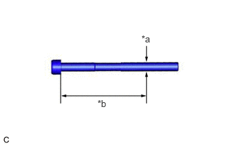
- Using a vernier caliper, measure the diameter of the threads at the measurement point.
*a Measurement Point *b 100 mm Standard Diameter
10.85 to 11.00 mm (0.427 to 0.433 in.)
Minimum Diameter
10.70 mm (0.421 in.)
Measurement Point (Distance from the Seat)
100 mm (3.94 in.)
HINT:
- If the diameter is less than the minimum, replace the cylinder head set bolt. Failure to do so may lead to engine damage.
- If there is any thread deformation, replace the cylinder head set bolt with a new one.
- Using a vernier caliper, measure the diameter of the threads at the measurement point.
- INSPECT CHAIN SUB-ASSEMBLY
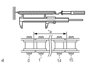
- Using a spring scale, pull the chain sub-assembly with a force of 147 N (15 kgf, 33.0 lbf) as shown in the illustration.
*a Measurement Length - Using a vernier caliper, measure the length of 15 links.
Maximum Chain Elongation
137.8 mm (5.43 in.)
HINT:
- Perform the measurement at 3 random places. Use the average of the measurements.
- If the average elongation is more than the maximum, replace the chain sub-assembly.
- Using a spring scale, pull the chain sub-assembly with a force of 147 N (15 kgf, 33.0 lbf) as shown in the illustration.
- INSPECT NO. 2 CHAIN SUB-ASSEMBLY
- Using a spring scale, pull the No. 2 chain sub-assembly with a force of 147 N (15 kgf, 33.0 lbf) as shown in the illustration.
*a Measurement Length - Using a vernier caliper, measure the length of 15 links.
Maximum Chain Elongation
137.8 mm (5.43 in.)
HINT:
- Perform the measurement at 3 random places. Use the average of the measurements.
- If the average elongation is more than the maximum, replace the No. 2 chain sub-assembly.
- Using a spring scale, pull the No. 2 chain sub-assembly with a force of 147 N (15 kgf, 33.0 lbf) as shown in the illustration.
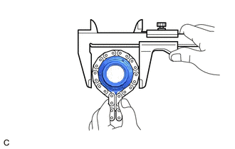
- INSPECT CRANKSHAFT TIMING SPROCKET
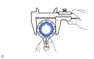
- Place the chain sub-assembly around the crankshaft timing sprocket.
- Using a vernier caliper, measure the diameter of the crankshaft timing sprocket with the chain sub-assembly.
Maximum Sprocket Diameter (with Chain Sub-assembly)
62.2 mm (2.45 in.)
HINT:
- The vernier caliper must contact the chain rollers when measuring.
- If the diameter is more than the maximum, replace the chain sub-assembly and crankshaft timing sprocket.
- INSPECT IDLE SPROCKET ASSEMBLY
- Place the chain sub-assembly around the idle sprocket assembly.
- Using a vernier caliper, measure the diameter of the idle sprocket assembly with the chain sub-assembly.
Maximum Sprocket Diameter (with Chain Sub-assembly)
65.2 mm (2.57 in.)
HINT:
- The vernier caliper must contact the chain rollers when measuring.
- If the diameter is more than the maximum, replace the chain sub-assembly and idle sprocket assembly.
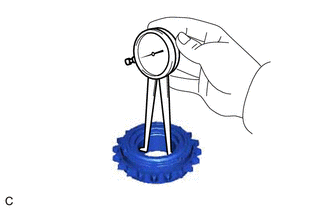
- INSPECT NO. 1 IDLE GEAR SHAFT OIL CLEARANCE
- Using a micrometer, measure the diameter of the No. 1 idle gear shaft.
Standard No. 1 Idle Gear Shaft Diameter
22.987 to 23.000 mm (0.905 to 0.906 in.)
- Using a caliper gauge, measure the inside diameter of the idle sprocket assembly.
Standard Idle Sprocket Assembly Inside Diameter
23.020 to 23.030 mm (0.906 to 0.907 in.)
- Subtract the No. 1 idle gear shaft diameter measurement from the idle sprocket assembly inside diameter measurement.
Standard Oil Clearance
0.020 to 0.043 mm (0.000787 to 0.00169 in.)
Maximum Oil Clearance
0.093 mm (0.00366 in.)
HINT:
If the oil clearance is more than the maximum, replace the No. 1 idle gear shaft and idle sprocket assembly.
- Using a micrometer, measure the diameter of the No. 1 idle gear shaft.
- INSPECT NO. 1 CHAIN TENSIONER ASSEMBLY
- INSPECT NO. 2 CHAIN TENSIONER ASSEMBLY
- INSPECT NO. 3 CHAIN TENSIONER ASSEMBLY
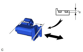
- INSPECT CHAIN TENSIONER SLIPPER
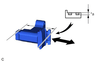
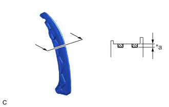
- INSPECT NO. 1 CHAIN VIBRATION DAMPER
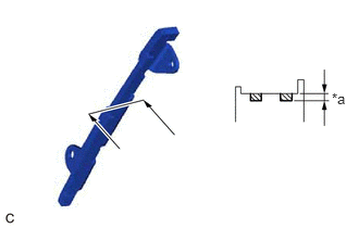
- INSPECT NO. 2 CHAIN VIBRATION DAMPER
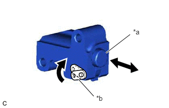
- INSPECT CAMSHAFT THRUST CLEARANCE
- Inspect the camshaft thrust clearance (for Bank 1).
- Install the camshaft.
See step 27
- Install the No. 2 camshaft.
See step 28
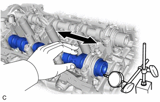
- Using a dial indicator, measure the thrust clearance while moving each camshaft back and forth.
Standard Thrust Clearance
0.08 to 0.13 mm (0.00315 to 0.00512 in.)
Maximum Thrust Clearance
0.18 mm (0.00709 in.)
HINT:
- If the thrust clearance is more than the maximum, replace the camshaft housing sub-assembly.
- If the thrust surface is damaged, replace the camshaft or No. 2 camshaft.
- Install the camshaft.
- Inspect the camshaft thrust clearance (for Bank 2).
- Install the No. 3 camshaft sub-assembly.
See step 15
- Install the No. 4 camshaft sub-assembly.
See step 16
- Using a dial indicator, measure the thrust clearance while moving each camshaft back and forth.
Standard Thrust Clearance
0.08 to 0.13 mm (0.00315 to 0.00512 in.)
Maximum Thrust Clearance
0.18 mm (0.00709 in.)
HINT:
- If the thrust clearance is more than the maximum, replace the camshaft housing sub-assembly LH.
- If the thrust surface is damaged, replace the No. 3 camshaft sub-assembly or No. 4 camshaft sub-assembly.
- Install the No. 3 camshaft sub-assembly.
- Inspect the camshaft thrust clearance (for Bank 1).
- INSPECT CAMSHAFT OIL CLEARANCE
- for Bank 1:
- Clean the camshaft bearing caps, camshaft housing sub-assembly and camshaft journals.
- Place the camshafts onto the camshaft housing sub-assembly.
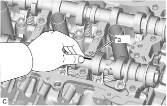
- Lay a strip of Plastigage across each camshaft journal.
*a Plastigage - Install the camshaft bearing caps.
See step 29
NOTE:Do not turn the camshaft.
- Remove the camshaft bearing caps.
See step 52
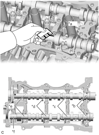
- Measure the Plastigage at its widest point.
*a Plastigage *b No. 1 Journal *c No. 2 journal *d No. 3 journal *e No. 4 journal *f No. 5 journal Standard Oil Clearance
Item Specified Condition No. 1 journal 0.032 to 0.063 mm (0.00126 to 0.00248 in.) No. 2, No. 3, No. 4 journals 0.025 to 0.062 mm (0.000984 to 0.00244 in.) No. 5 journal 0.015 to 0.052 mm (0.000591 to 0.00205 in.) Maximum Oil Clearance
Item Specified Condition No. 1 journal 0.10 mm (0.00394 in.) No. 2, No. 3, No. 4 journals 0.10 mm (0.00394 in.) No. 5 journal 0.10 mm (0.00394 in.) HINT:
- If the oil clearance is more than the maximum, replace the camshaft or No. 2 camshaft.
- If necessary, replace the camshaft housing sub-assembly.
- for Bank 2:
- Clean the camshaft bearing caps, camshaft housing sub-assembly LH and camshaft journals.
- Place the camshafts on the camshaft housing sub-assembly LH.
- Lay a strip of Plastigage across each camshaft journal.
*a Plastigage - Install the camshaft bearing caps.
See step 17
NOTE:Do not turn the camshaft.
- Remove the camshaft bearing caps.
See step 58
- Measure the Plastigage at its widest point.
*a Plastigage *b No. 1 Journal *c Other Journals Standard Oil Clearance
Item Specified Condition No. 1 journal 0.032 to 0.063 mm (0.00126 to 0.00248 in.) Other journals 0.025 to 0.062 mm (0.000984 to 0.00244 in.) Maximum Oil Clearance
Item Specified Condition No. 1 journal 0.10 mm (0.00394 in.) Other journals 0.10 mm (0.00394 in.) HINT:
- If the oil clearance is more than the maximum, replace the No. 3 camshaft sub-assembly or No. 4 camshaft sub-assembly.
- If necessary, replace the camshaft housing sub-assembly LH.
- for Bank 1:
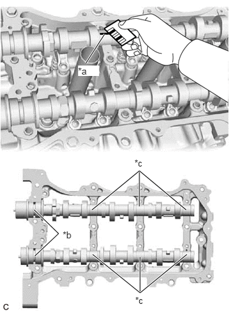
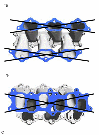
- INSPECT INTAKE MANIFOLD
*a Cylinder Head Side *b Surge Tank Side - Cylinder head side:
- Using a precision straightedge and feeler gauge, check the surface which contacts the cylinder head sub-assembly and cylinder head LH for warpage.
Maximum Warpage
0.1 mm (0.00394 in.)
HINT:
If the warpage is more than the maximum, replace the intake manifold.
- Using a precision straightedge and feeler gauge, check the surface which contacts the cylinder head sub-assembly and cylinder head LH for warpage.
- Surge tank side:
- Using a precision straightedge and feeler gauge, check the surface which contacts the intake air surge tank assembly for warpage.
Maximum Warpage
0.1 mm (0.00394 in.)
HINT:
If the warpage is more than the maximum, replace the intake manifold.
- Using a precision straightedge and feeler gauge, check the surface which contacts the intake air surge tank assembly for warpage.
- Cylinder head side:
- INSPECT EXHAUST MANIFOLD