Replacement [12/2019 - 10/2022]: Procedure
- REPLACE INTAKE VALVE GUIDE BUSH
- Heat the cylinder head LH to between 80 and 100°C (176 and 212°F).
- Place the cylinder head LH on wooden blocks.WARNING:
Be sure to wear protective gloves.
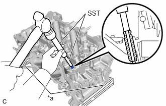
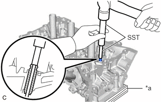
- Using SST and a hammer, tap out the intake valve guide bush.
*a Wooden Block - SST: 09201-10000
- 09201-01050
- SST: 09950-70010
- 09951-07100
- SST: 09201-10000
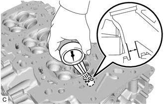
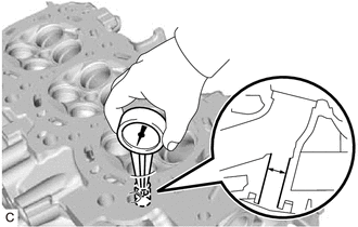
- Using a caliper gauge, measure the intake valve guide bush bore diameter of the cylinder head LH.
Standard Intake Valve Guide Bush Bore Diameter
10.285 to 10.306 mm (0.405 to 0.406 in.)
New Guide Bush Selection Chart
Bush Size Bush Bore Diameter STD 10.333 to 10.344 mm (0.40681 to 0.40724 in.) O/S 0.05 10.383 to 10.394 mm (0.40878 to 0.40921 in.) HINT:
- If the intake valve guide bush bore diameter is more than 10.306 mm (0.406 in.), machine the intake valve guide bush bore to a dimension of 10.335 to 10.356 mm (0.407 to 0.408 in.) to install an O/S 0.05 intake valve guide bush.
- If the intake valve guide bush bore diameter of the cylinder head LH is more than 10.356 mm (0.40772 in.), replace the cylinder head LH.
- Heat the cylinder head LH to between 80 and 100°C (176 and 212°F).
- Place the cylinder head LH on wooden blocks.WARNING:
Be sure to wear protective gloves.
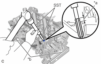
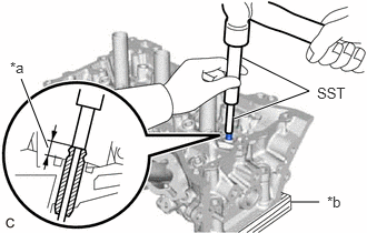
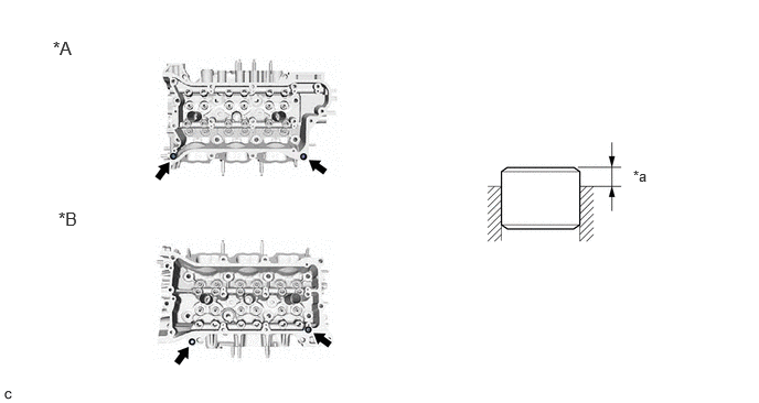
- Using SST and a hammer, tap in a new intake valve guide bush to the specified protrusion height.
*a Protrusion Height *b Wooden Block - SST: 09201-10000
- 09201-01050
- SST: 09950-70010
- 09951-07100
Standard Protrusion Height
9.30 to 9.70 mm (0.366 to 0.382 in.)
- SST: 09201-10000
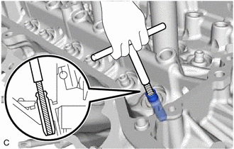
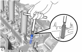
- Using a sharp 5.5 mm reamer, ream the intake valve guide bush to obtain the specified oil clearance.
Standard Oil Clearance
0.025 to 0.060 mm (0.000984 to 0.00236 in.)
- REPLACE EXHAUST VALVE GUIDE BUSH
- Heat the cylinder head LH to between 80 and 100°C (176 and 212°F).
- Place the cylinder head LH on wooden blocks.WARNING:
Be sure to wear protective gloves.
- Using SST and a hammer, tap out the exhaust valve guide bush.
- SST: 09201-10000
- 09201-01050
- SST: 09950-70010
- 09951-07100
*a Wooden Block - SST: 09201-10000
- Using a caliper gauge, measure the exhaust valve guide bush bore diameter of the cylinder head LH.
Standard Exhaust Valve Guide Bush Bore Diameter
10.285 to 10.306 mm (0.405 to 0.406 in.)
New Guide Bush Selection Chart
Bush Size Bush Bore Diameter STD 10.333 to 10.344 mm (0.40681 to 0.40724 in.) O/S 0.05 10.383 to 10.394 mm (0.40878 to 0.40921 in.) HINT:
- If the exhaust valve guide bush bore diameter is more than 10.306 mm (0.406 in.), machine the exhaust valve guide bush bore to a dimension of 10.335 to 10.356 mm (0.407 to 0.408 in.) to install an O/S 0.05 exhaust valve guide bush.
- If the exhaust valve guide bush bore diameter of the cylinder head LH is more than 10.356 mm (0.40772 in.), replace the cylinder head LH.
- Heat the cylinder head LH to between 80 and 100°C (176 and 212°F).
- Place the cylinder head LH on wooden blocks.WARNING:
Be sure to wear protective gloves.
- Using SST and a hammer, tap in a new exhaust valve guide bush to the specified protrusion height.
*a Protrusion Height *b Wooden Block - SST: 09201-10000
- 09201-01050
- SST: 09950-70010
- 09951-07100
Standard Protrusion Height
9.30 to 9.70 mm (0.366 to 0.382 in.)
- SST: 09201-10000
- Using a sharp 5.5 mm reamer, ream the exhaust valve guide bush to obtain the specified oil clearance.
Standard Oil Clearance
0.030 to 0.065 mm (0.00118 to 0.00256 in.)
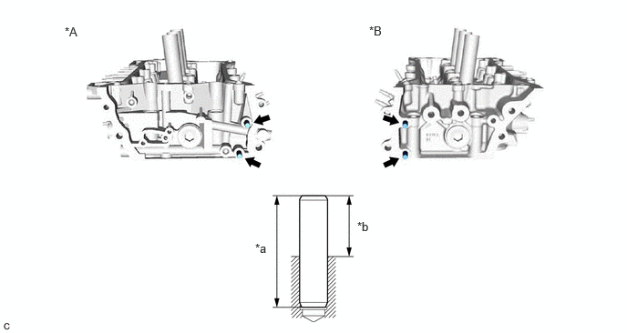
- REPLACE RING PIN
HINT:
It is not necessary to remove the ring pins unless they are being replaced.
- REPLACE STUD BOLT
HINT:
If a stud bolt is deformed or its threads are damaged, replace it.
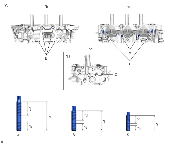
- Using E6 and E8 "TORX" socket wrenches, install the stud bolts to the cylinder head LH.
*A for Bank 2 *B w/ Stud Bolt *a Intake Side *b Exhaust Side *c Rear Side *d 20 mm (0.787 in.) *e 13 mm (0.512 in.) *f 35 mm (1.38 in.) *g 16 mm (0.630 in.) *h 9 mm (0.354 in.) *i 27 mm (1.06 in.) *j 26 mm (1.02 in.) *k 16.7 mm (0.657 in.) *l 51.7 mm (2.04 in.) Bolt (A), (B)
Torque: 10 N.m (102 kgf/cm, 7 ft.lbf)
Bolt (C)
Torque: 4.0 N.m (41 kgf/cm, 35 in.lbf)
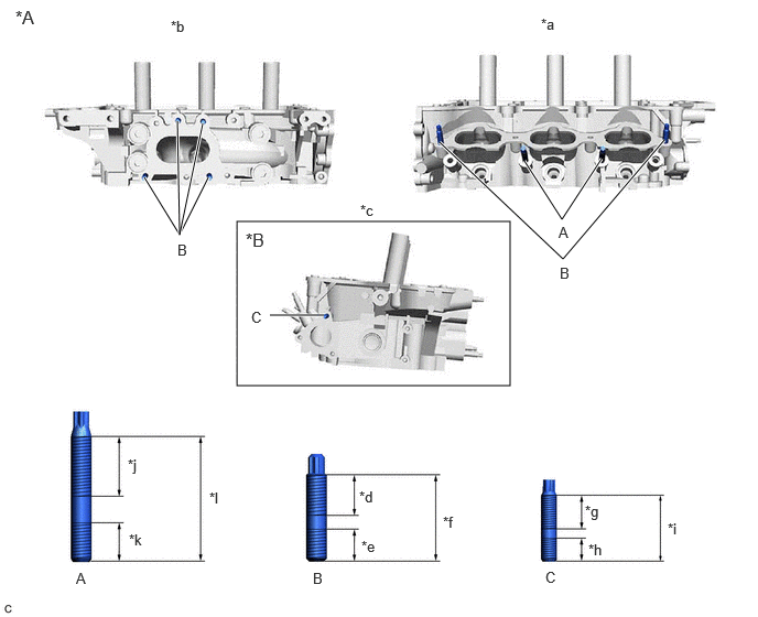
- Using E6 and E8 "TORX" socket wrenches, install the stud bolts to the cylinder head sub-assembly.
*A for Bank 1 *B w/ Stud Bolt *a Intake Side *b Exhaust Side *c Rear Side *d 20 mm (0.787 in.) *e 13 mm (0.512 in.) *f 35 mm (1.38 in.) *g 16 mm (0.630 in.) *h 9 mm (0.354 in.) *i 27 mm (1.06 in.) *j 26 mm (1.02 in.) *k 16.7 mm (0.657 in.) *l 51.7 mm (2.04 in.) Bolt (A), (B)
Torque: 10 N.m (102 kgf/cm, 7 ft.lbf)
Bolt (C)
Torque: 4.0 N.m (41 kgf/cm, 35 in.lbf)
- Using E6 and E8 "TORX" socket wrenches, install the stud bolts to the cylinder head LH.
- REPLACE STRAIGHT PIN
HINT:
If a straight pin is deformed, replace it.