On-Vehicle Inspection [12/2019 - 11/2023]: Procedure
WARNING: This page is about a different variant/trim than selected.
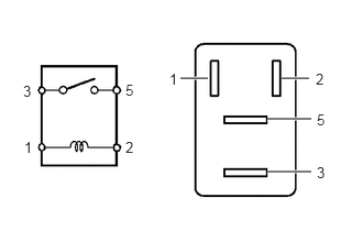
- INSPECT NO. 1 ELECTRONIC FUEL INJECTION MAIN RELAY (EFI-MAIN NO. 1)
- Measure the resistance according to the value(s) in the table below.
Standard Resistance
Tester Connection Condition Specified Condition 3 - 5 Auxiliary battery voltage not applied between terminals 1 and 2 10 kΩ or higher Auxiliary battery voltage applied between terminals 1 and 2 Below 1 Ω If the result is not as specified, replace the No. 1 electronic fuel injection main relay (EFI-MAIN NO. 1).
- Measure the resistance according to the value(s) in the table below.
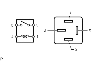
- INSPECT NO. 2 ELECTRONIC FUEL INJECTION MAIN RELAY (EFI-MAIN NO. 2)
- Measure the resistance according to the value(s) in the table below.
Standard Resistance
Tester Connection Condition Specified Condition 3 - 5 Auxiliary battery voltage not applied between terminals 1 and 2 10 kΩ or higher Auxiliary battery voltage applied between terminals 1 and 2 Below 1 Ω If the result is not as specified, replace the No. 2 electronic fuel injection main relay (EFI-MAIN NO. 2).
- Measure the resistance according to the value(s) in the table below.
- INSPECT NO. 3 ELECTRONIC FUEL INJECTION MAIN RELAY (EFI-MAIN NO. 3)
- Measure the resistance according to the value(s) in the table below.
Standard Resistance
Tester Connection Condition Specified Condition 3 - 5 Auxiliary battery voltage not applied between terminals 1 and 2 10 kΩ or higher Auxiliary battery voltage applied between terminals 1 and 2 Below 1 Ω If the result is not as specified, replace the No. 3 electronic fuel injection main relay (EFI-MAIN NO. 3).
- Measure the resistance according to the value(s) in the table below.
- INSPECT INJECTOR RELAY (D INJ)
- Measure the resistance according to the value(s) in the table below.
Standard Resistance
Tester Connection Condition Specified Condition 3 - 5 Auxiliary battery voltage not applied between terminals 1 and 2 10 kΩ or higher Auxiliary battery voltage applied between terminals 1 and 2 Below 1 Ω If the result is not as specified, replace the injector relay (D INJ).
- Measure the resistance according to the value(s) in the table below.
- INSPECT VVT RELAY (VVT)
- Measure the resistance according to the value(s) in the table below.
Standard Resistance
Tester Connection Condition Specified Condition 3 - 5 Auxiliary battery voltage not applied between terminals 1 and 2 10 kΩ or higher Auxiliary battery voltage applied between terminals 1 and 2 Below 1 Ω If the result is not as specified, replace the VVT relay (VVT).
- Measure the resistance according to the value(s) in the table below.
- INSPECT NO. 2 IGNITION RELAY (IG2 NO. 1)
- Measure the resistance according to the value(s) in the table below.
Standard Resistance
Tester Connection Condition Specified Condition 3 - 5 Auxiliary battery voltage not applied between terminals 1 and 2 10 kΩ or higher Auxiliary battery voltage applied between terminals 1 and 2 Below 1 Ω If the result is not as specified, replace the No. 2 ignition relay (IG2 NO. 1).
- Measure the resistance according to the value(s) in the table below.