Installation [12/2019 - ]: Procedure
- INSTALL SST
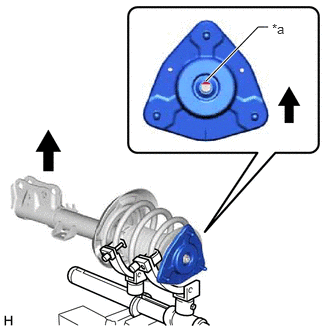
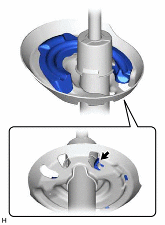
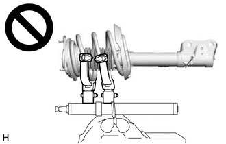
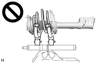
- Align the slot on end of the shock rod of the front shock absorber assembly as shown in the illustration.
- Install SST (09727-58100) and SST (09727-58130) to the front shock absorber assembly.
- SST: 09727-58100
- SST: 09727-58130
- SST: 09727-58010
- 09727-58030
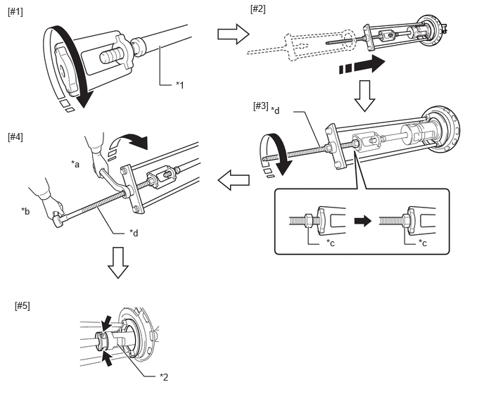
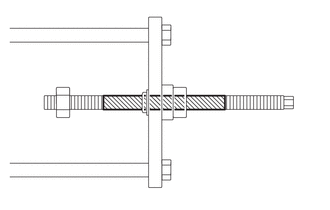
*1 Front Shock Absorber Assembly *2 Shock Absorber Outer Shell *a Turn *b Hold *c Fixing Nut *d Bolt NOTE:Apply molybdenum grease to the bolt (area with diagonal lines) of SST (09727-58010).

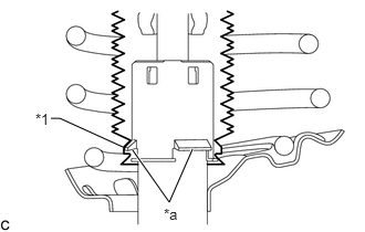
Application Area - Install SST (09727-58030) to the end of the shock rod of the front shock absorber assembly.[#1]
- Install SST (09727-58010) to the front shock absorber assembly.[#2]NOTE:
Take due care when installing SST (09727-58010) to ensure the shock rod is not damaged.
- Secure the SST (09727-58010) bolt and SST (09727-58030) with the fixing nut.[#3]
- After securing the SST (09727-58010) bolt, rotate the nut clockwise.[#4]
HINT:
Extend the shock rod to its maximum length to install SST (09727-58100) and SST (09727-58130).
- Using a piece of cloth, etc., clean the shock rod and remove any foreign matter and oil.NOTE:
Thoroughly clean the shock rod to prevent damage to the shock rod due to contact of foreign matter.
- Clean the surface of SST (09727-58130) to which the front shock absorber assembly is installed and remove any foreign matter and oil.
*a Installation Surface NOTE:Thoroughly clean the installation surface to prevent damage to the shock rod due to contact of foreign matter.
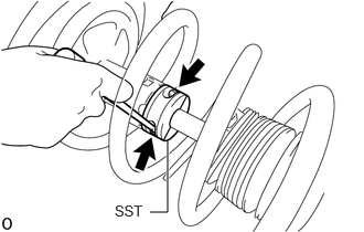
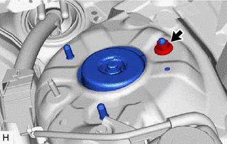
- Using a long ball hexagon 5, install SST (09727-58100) and SST (09727-58130) to the shock rod.[#5]NOTE:
Before installing, check the position of the slot on end of the shock rod.
HINT:
Install SST (09727-58100) and SST (09727-58130) to the base of the shock rod and check that SST (09727-58100) and SST (09727-58130) are securing the shock rod.
- After securing the SST (09727-58010) bolt, rotate the nut counterclockwise.
- Check that the shock rod and SST (09727-58030) have become free before releasing the fixing nut and removing SST (09727-58010) from the end of the shock rod.NOTE:
Take due care when removing SST (09727-58010) to ensure the shock rod is not damaged.
- Remove SST (09727-58030) from the end of the shock rod.
- Using a piece of cloth, etc., clean the end of the shock rod threads and remove any foreign matter and oil.
- INSTALL FRONT LOWER COIL SPRING INSULATOR
- INSTALL FRONT SPRING BUMPER
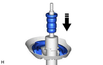
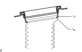
- Install the front spring bumper to the front shock absorber assembly.

Install in this direction NOTE:- Face the smaller diameter end of the front spring bumper downward.
- Do not apply lubricants to the front spring bumper.
- Do not apply lubricants to the front shock absorber assembly cap or rod.
- Do not clean the front spring bumper with water or solvent.
- Install the front spring bumper to the front shock absorber assembly.
- INSTALL FRONT COIL SPRING
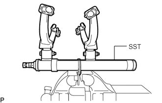
- Secure SST in a vise.
- SST: 09727-00051
- SST: 09727-30022
- 09727-00010
- 09727-00031
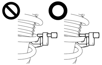
- Attach the hooks of each SST arm across the diameter of the coil spring.WARNING:
- Make sure that the hooks are securely attached to the coil spring.
- If a hook disengages from the coil spring, the coil spring may fly out, resulting in injury.
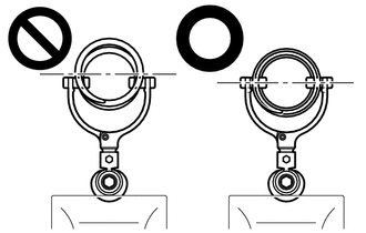
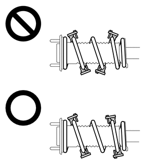
- Make sure that the hooks of the upper and lower SST arms are attached to the coil spring so that the distance between the hooks is as large as possible.
- If a hook disengages from the coil spring, the coil spring may fly out, resulting in injury.
- Make sure that the arms of SST are parallel and the number of coils between the arms is the same on each side.
- If a hook disengages from the coil spring, the coil spring may fly out, resulting in injury.
- Make sure that the hooks are securely attached to the coil spring.
- Install the stopper pins to the hooks of SST.
- Using SST, compress the coil spring.WARNING:
- If the coil spring starts to bow out while using SST, stop immediately and reattach SST correctly.
- If a hook disengages from the coil spring, the coil spring may fly out, resulting in injury.
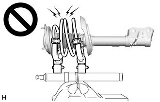
- Do not compress the coil spring to the point where the coils touch each other.
- If a hook disengages from the coil spring, the coil spring may fly out, resulting in injury.
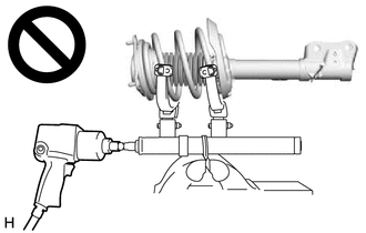
- Do not use an impact wrench.
- If an impact wrench is used, the threads of SST may be damaged, or sudden compression of the coil spring may cause a hook to disengage and the coil spring to fly out, resulting in injury.
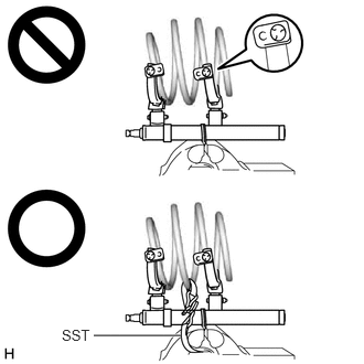
- If a stopper pin touches the coil spring while using SST, remove the stopper pin and continue with the procedure.
- If a stopper pin is removed, install a coil spring stopper belt as shown in the illustration.
- If a hook disengages from the coil spring, the coil spring may fly out, resulting in injury.
- SST: 09727-00110
- If the coil spring starts to bow out while using SST, stop immediately and reattach SST correctly.
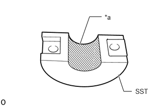
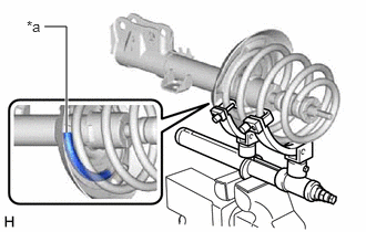
- Align the end of the front coil spring with the flange of the front lower coil spring insulator and install the front coil spring.
*a Depression NOTE:Make sure to fit the end of the front coil spring that has the larger diameter into the depression of the front lower coil spring insulator.
- Secure SST in a vise.
- INSTALL STRUT MOUNTING BEARING
- INSTALL FRONT UPPER COIL SPRING INSULATOR
- Install the front upper coil spring insulator to the strut mounting bearing.
- INSTALL STRUT MOUNTING BEARING WITH DUST COVER
- Install the strut mounting bearing with dust cover to the front shock absorber assembly.
- INSTALL FRONT SUSPENSION SUPPORT SUB-ASSEMBLY
- Install the front suspension support sub-assembly as shown in the illustration.
*a Slot 
Outside of the Vehicle NOTE:Check that the slot on the shock rod and the slot on the front suspension support sub-assembly are aligned.
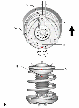
- Align the stud bolt of the front suspension support sub-assembly with the front shock absorber lower bracket as shown in the illustration.
*a 0° +/- 3° *b 15° *c Stud Bolt of Front Suspension Support Sub-assembly *d Guide Line of Front Suspension Support Sub-assembly *e Alignment Mark of Strut Mounting Bearing *f Front Shock Absorber Lower Bracket *g Arrow of Front No. 1 Shock Absorber Dust Cover Outside of the Vehicle NOTE:Make sure to install the stud bolt of the front suspension support sub-assembly so that it is aligned within +/- 3° of the center of the front shock absorber lower bracket.
- Align the alignment mark of the strut mounting bearing with the guide line of the front suspension support sub-assembly as shown in the illustration.NOTE:
Make sure to install the strut mounting bearing so that the alignment mark of the strut mounting bearing is aligned within +/- 15° of the guide line of the front suspension support sub-assembly.
- Align the arrow of the front No. 1 shock absorber dust cover with the alignment mark of the strut mounting bearing as shown in the illustration.
- Install the front suspension support sub-assembly as shown in the illustration.
- TEMPORARILY TIGHTEN FRONT SUPPORT TO FRONT SHOCK ABSORBER NUT
- Temporarily tighten a new front support to front shock absorber nut.
- Remove SST from the front coil spring.NOTE:
Do not use an impact wrench. It will damage SST.
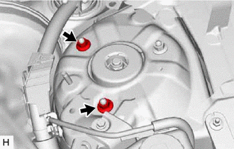
- Fold back the front No. 1 shock absorber dust cover and then use a long ball hexagon 5 to remove SST (09727-58100) and SST (09727-58130) from the front shock absorber assembly.NOTE:
- Thoroughly remove SST (09727-58100) and SST (09727-58130).
- Check that front No. 1 shock absorber dust cover is not excessively deformed or crushed.
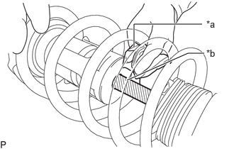
- Using a piece of cloth, etc., clean the shock rod of the front shock absorber assembly and remove any foreign matter and oil.NOTE:
Thoroughly clean the shock rod to prevent damage to the front shock absorber assembly due to contact of foreign matter.
*a Cloth, etc. *b Shock Rod
- CONNECT FRONT NO. 1 SHOCK ABSORBER DUST COVER
- Connect the end of the front No. 1 shock absorber dust cover with the claws of the front shock absorber assembly.NOTE:
- Make sure that the end of the front No. 1 shock absorber dust cover is securely attached to the claws of the front shock absorber assembly.
- Make sure there is no excessive damage to the bellows of the front No. 1 shock absorber dust cover.
- Do not allow oil, grease, etc., to contact the front No. 1 shock absorber dust cover.
- If there is oil or grease on the insulator, wipe clean with a cloth. Do not use an alcohol based cleaner.
*1 Front No. 1 Shock Absorber Dust Cover *a Claw
- Connect the end of the front No. 1 shock absorber dust cover with the claws of the front shock absorber assembly.
- INSTALL FRONT SHOCK ABSORBER WITH COIL SPRING
- Install the front shock absorber with coil spring (upper side) with the nut.
Torque: 50 N.m (510 kgf/cm, 37 ft.lbf)
- Temporarily install the 2 nuts to the front shock absorber assembly.
- Install the front shock absorber with coil spring (lower side) to the steering knuckle with the 2 bolts and 2 nuts.
Torque: 290 N.m (2957 kgf/cm, 214 ft.lbf)
NOTE:- When installing the nuts, keep the bolts from rotating.
- Do not apply lubricants to the steering knuckle and shock absorber contact surfaces.
HINT:
The bolts can be installed in either direction, however, make sure that they are both installed in the same direction.
- Install the front shock absorber with coil spring (upper side) with the nut.
- INSTALL FRONT SPEED SENSOR
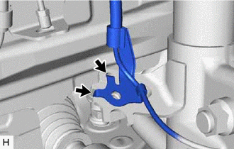
- Engage the 2 hooks to install the front speed sensor clamp bracket.
Hook NOTE:Do not twist the front speed sensor when installing it.
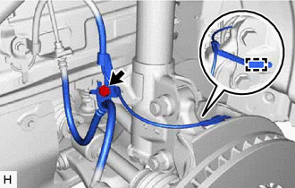
- Install the front speed sensor and front flexible hose to the front shock absorber assembly with the bolt.
Torque: 29 N.m (296 kgf/cm, 21 ft.lbf)
NOTE:Do not twist the front flexible hose when installing it.
- Engage the clamp.NOTE:
Do not twist the front speed sensor when installing it.
- Engage the 2 hooks to install the front speed sensor clamp bracket.
- INSTALL FRONT STABILIZER LINK ASSEMBLY
- Install the front stabilizer link assembly to the front shock absorber assembly with the nut.
Torque: 74 N.m (755 kgf/cm, 55 ft.lbf)
HINT:
If the ball joint turns together with the nut, use a 6 mm hexagon socket wrench to hold the stud bolt.
- Install the front stabilizer link assembly to the front shock absorber assembly with the nut.
- FULLY TIGHTEN FRONT SUPPORT TO FRONT SHOCK ABSORBER NUT
- INSTALL COWL VENTILATOR PANEL SUB-ASSEMBLY
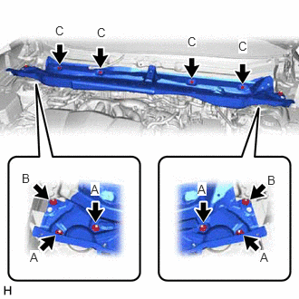
- Install the cowl ventilator panel sub-assembly with the 4 bolts and 6 nuts.
Nut (A)
Torque: 50 N.m (510 kgf/cm, 37 ft.lbf)
Nut (B)
Torque: 20 N.m (204 kgf/cm, 15 ft.lbf)
Bolt (C)
Torque: 8.0 N.m (82 kgf/cm, 71 in.lbf)
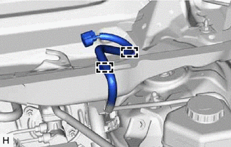
- Engage the 2 clamps to install the wire harness to the cowl ventilator panel sub-assembly.
- Engage the 2 clamps to install the wire harness to the cowl ventilator panel sub-assembly.
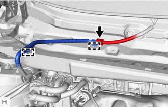
- Connect the connector.
- Install the cowl ventilator panel sub-assembly with the 4 bolts and 6 nuts.
- INSTALL FRONT UPPER SUSPENSION TO COWL BRACE SUB-ASSEMBLY LH
- Install the front upper suspension to cowl brace sub-assembly LH to the cowl ventilator panel sub-assembly with the 2 nuts.
Torque: 20 N.m (204 kgf/cm, 15 ft.lbf)
- Install the front upper suspension to cowl brace sub-assembly LH to the cowl ventilator panel sub-assembly with the 2 nuts.
- INSTALL FRONT UPPER SUSPENSION TO COWL BRACE SUB-ASSEMBLY RH
HINT:
Perform the same procedure as for the LH side.
- INSTALL FRONT FENDER SPLASH SHIELD SEAL FRONT LH
- Install the front fender splash shield seal front LH.
- INSTALL FRONT FENDER SPLASH SHIELD SEAL FRONT RH
HINT:
Perform the same procedure as for the LH side.
- INSTALL FENDER SPLASH SHIELD SUB-ASSEMBLY REAR LH
- Install the fender splash shield sub-assembly rear LH with the clip.
- INSTALL FENDER SPLASH SHIELD SUB-ASSEMBLY REAR RH
HINT:
Perform the same procedure as for the LH side.
- INSTALL WINDSHIELD WIPER MOTOR AND LINK ASSEMBLY
Refer to INSTALLATION [12/2019 - ]
- INSTALL FRONT WHEEL
Refer to INSTALLATION [12/2019 - 10/2022] , or refer to INSTALLATION [10/2022 - ]
- INSPECT AND ADJUST FRONT WHEEL ALIGNMENT
Refer to ADJUSTMENT [12/2019 - 09/2020] , or refer to ADJUSTMENT [09/2020 - 10/2022] , or refer to ADJUSTMENT [10/2022 - 11/2023] , or refer to ADJUSTMENT [11/2023 - 11/2024] , or refer to ADJUSTMENT [11/2024 - ]
- PERFORM INITIALIZATION
Parking Assist Monitor System Refer to CALIBRATION [12/2019 - 10/2022] , or refer to CALIBRATION [10/2022 - ] Panoramic View Monitor System Refer to CALIBRATION [12/2019 - 10/2022] , or refer to CALIBRATION [10/2022 - 11/2023] , or refer to CALIBRATION [11/2023 - ] Lighting System (EXT) (w/ AFS) Refer to INITIALIZATION [12/2019 - 11/2023] , or refer to INITIALIZATION [11/2023 - ]