DTC P0688-1F: ECM/PCM Power Relay Sense Circuit Intermittent [12/2019 - 11/2023]: Procedure
- CHECK AUXILIARY BATTERY TERMINAL
- Confirm whether the auxiliary battery terminals have been disconnected recently.
Result
Result Proceed to Terminals have been disconnected. A Terminals have not been disconnected. B
Result:
B
See step 5
Result:
A
See step 2
- Confirm whether the auxiliary battery terminals have been disconnected recently.
- CONFIRM MASTER WARNING
- Turn the ignition switch to ON (READY) from off.
- Confirm that the master warning illuminates.
Result
Result Proceed to Master warning illuminates. A Master warning does not illuminate. B NOTE:DTC P0688-1F may be stored after disconnecting and reconnecting the auxiliary battery terminals. If this happens, the DTC will not be output if the ignition switch is turned off and then ON (READY) again. In this case, clear the DTCs to complete the inspection.
- Turn the ignition switch off.
Result:
B
END
Result:
A
See step 3
- CLEAR DTC
- Read and record the DTCs and Freeze Frame Data.
Powertrain > Hybrid Control > Trouble Codes
- Clear the DTCs and Freeze Frame Data.
Powertrain > Hybrid Control > Clear DTCs
- Turn the ignition switch off and wait for 2 minutes or more.
Result
Proceed to NEXT
Result:
NEXT
See step 4
- Read and record the DTCs and Freeze Frame Data.
- CHECK DTC OUTPUT (HYBRID CONTROL)
- Check for DTCs.
Powertrain > Hybrid Control > Trouble Codes
Result
Result Proceed to DTC P0688-1F is output again. A DTCs other than P0688-1F are also output. B - Turn the ignition switch off.
Result:
B
GO TO DTC CHART (HYBRID CONTROL SYSTEM). Refer to DIAGNOSTIC TROUBLE CODE CHART [12/2019 - 09/2020] , or refer to DIAGNOSTIC TROUBLE CODE CHART [09/2020 - 10/2021] , or refer to DIAGNOSTIC TROUBLE CODE CHART [10/2021 - 11/2023]
Result:
A
See step 5
- Check for DTCs.
- CHECK AUXILIARY BATTERY TERMINAL (CONTACT PROBLEM)
- Check the connection of the auxiliary battery terminal.
OK
The terminal is connected securely and there is no contact problem.
Result
Proceed to OK NG
Result:
NG
CONNECT SECURELY
Result:
OK
See step 6
- Check the connection of the auxiliary battery terminal.
- CHECK CONNECTOR CONNECTION CONDITION (HYBRID VEHICLE CONTROL ECU CONNECTOR)
See step 1
Result
Proceed to OK NG Result:
NG
CONNECT SECURELY
Result:
OK
See step 7
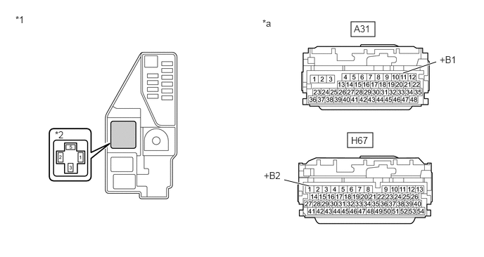
- CHECK HARNESS AND CONNECTOR (HYBRID VEHICLE CONTROL ECU - IGCT RELAY)
- Remove the IGCT relay from the No. 5 floor relay block and No. 5 floor junction block assembly.
- Disconnect the A31 and H67 hybrid vehicle control ECU connectors.
- Measure the resistance according to the value(s) in the table below.
*1 No. 5 Floor Relay Block and No. 5 Floor Junction Block Assembly *2 IGCT Relay Holder *a Front view of wire harness connector
(to Hybrid Vehicle Control ECU)- - Standard Resistance
Tester Connection Condition Specified Condition A31-11 (+B1) - 5 (IGCT relay holder) Ignition switch off Below 1 Ω H67-1 (+B2) - 5 (IGCT relay holder) Ignition switch off Below 1 Ω - Reconnect the A31 and H67 hybrid vehicle control ECU connectors.
- Reinstall the IGCT relay.
Result
Proceed to OK NG
Result:
NG
REPAIR OR REPLACE HARNESS OR CONNECTOR
Result:
OK
See step 8
- CHECK FOR INTERMITTENT PROBLEMS
- Check for intermittent problems.
Refer to CHECK FOR INTERMITTENT PROBLEMS [12/2019 - 11/2023]
- Check the connection and terminal contact pressure of the connectors and wire harnesses between the hybrid vehicle control ECU and the No. 5 floor relay block and No. 5 floor junction block assembly.
- When the ignition switch is ON (READY), jiggle the connectors and wire harnesses between the hybrid vehicle control ECU and the No. 5 floor relay block and No. 5 floor junction block assembly.
Result
Result Proceed to Problem symptom does not recur. A Problem symptom recurs. B
Result:
A
REPLACE HYBRID VEHICLE CONTROL ECU. Refer to REMOVAL [12/2019 - 10/2022] , or refer to REMOVAL [10/2022 - 11/2023]
Result:
B
REPAIR OR REPLACE MALFUNCTIONING PARTS, COMPONENT AND AREA
- Check for intermittent problems.