DTC P0A0A-13: High Voltage System Interlock Circuit Open; DTC P0A0A-92: High Voltage System Interlock Performance or Incorrect Operation [12/2019 - 11/2023]: Procedure
- CHECK DTC OUTPUT (HYBRID CONTROL)
- Check for DTCs.
Powertrain > Hybrid Control > Trouble Codes
Result
Result Proceed to P0A0A-13 or P0A0A-92 only is output, or DTCs except the ones in the table below are also output. A Any of the following DTCs are also output. B Malfunction Content Relevant DTC Microcomputer malfunction P0606-47 Hybrid/EV Powertrain Control Module Processor Watchdog / Safety MCU Failure P0606-87 Hybrid/EV Powertrain Control Module Processor to Monitoring Processor Missing Message P060A-47 Hybrid/EV Powertrain Control Module Monitoring Processor Watchdog / Safety MCU Failure P060A-87 Hybrid/EV Powertrain Control Module Processor from Monitoring Processor Missing Message P060B-49 Hybrid/EV Powertrain Control Module A/D Processing Internal Electronic Failure P060B-71 Hybrid/EV Powertrain Control Module A/D Processing Actuator Stuck P060B-1C Hybrid/EV Powertrain Control Module A/D Processing Voltage Out of Range P1CE3-49 Hybrid/EV Powertrain Control Module Monitoring Processor A/D Processing Internal Electronic Failure P1CE3-71 Hybrid/EV Powertrain Control Module Monitoring Processor A/D Processing Actuator Stuck P1CE3-1C Hybrid/EV Powertrain Control Module Monitoring Processor A/D Processing Voltage Out of Range P060A-45 Hybrid/EV Powertrain Control Module Monitoring Processor Program Memory Failure P060A-44 Hybrid/EV Powertrain Control Module Monitoring Processor Data Memory Failure P060A-29 Hybrid/EV Powertrain Control Module Monitoring Processor Signal Invalid P060A-49 Hybrid/EV Powertrain Control Module Monitoring Processor Internal Electronic Failure Power source circuit malfunction P0688-1F ECM/PCM Power Relay Sense Circuit Intermittent System malfunction P1C9E-9F Hybrid/EV System Reset Stuck Off HINT:
- P0A0A-13 or P0A0A-92 may be output as a result of the malfunction indicated by the DTCs above.
- The chart above is listed in inspection order of priority.
- Check DTCs that are output at the same time by following the listed order. (The main cause of the malfunction can be determined without performing unnecessary inspections.)
- P0A0A-13 or P0A0A-92 may be output as a result of the malfunction indicated by the DTCs above.
- Turn the ignition switch off.
Result:
B
GO TO DTC CHART (HYBRID CONTROL SYSTEM)
Refer to DIAGNOSTIC TROUBLE CODE CHART [12/2019 - 09/2020] , or refer to DIAGNOSTIC TROUBLE CODE CHART [09/2020 - 10/2021] , or refer to DIAGNOSTIC TROUBLE CODE CHART [10/2021 - 11/2023]
Result:
A
See step 2
- Check for DTCs.
- CLEAR DTC
See step 3
Result
Proceed to NEXT Result:
NEXT
See step 3
- CHECK DTC OUTPUT (HYBRID CONTROL)
- Check if DTCs are output.
Powertrain > Hybrid Control > Trouble Codes
Result
Result Proceed to P0A0A-13 or P0A0A-92 is output again. A Neither P0A0A-13 or P0A0A-92 is output again. B - Turn the ignition switch off.
Result:
B
See step 10
Result:
A
See step 4
- Check if DTCs are output.
- CHECK SERVICE PLUG GRIP WARNING:
Be sure to wear insulated gloves.
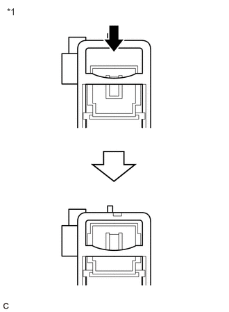
- Check if the service plug grip is installed correctly.NOTE:
Insert the service plug grip until a click sound is heard.
HINT:
- For the removal and installation procedures.
Refer to REMOVAL [12/2019 - 10/2022] , or refer to REMOVAL [10/2022 - 11/2023]
- P0A0A-92 is also set if the ignition switch is turned to ON with the service plug grip removed. Confirm the conditions when the malfunction occurred.
*1 Service Plug Grip Result
Proceed to OK NG - For the removal and installation procedures.
Result:
NG
INSTALL PARTS CORRECTLY
Result:
OK
See step 5
- Check if the service plug grip is installed correctly.
- CHECK CONNECTOR CONNECTION CONDITION (INTERLOCK CONNECTOR) WARNING:
Be sure to wear insulated gloves.
- Check that the service plug grip is not installed.NOTE:
After removing the service plug grip, do not turn the ignition switch to ON (READY), unless instructed by the repair information because this may cause a malfunction.
- Remove the No. 10 HV battery shield panel.
Refer to REMOVAL [12/2019 - 10/2022] , or refer to REMOVAL [10/2022 - 11/2023]
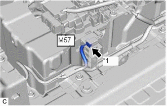
- Check that the interlock connector at the service plug grip installation socket is connected correctly.
OK
The connector is connected correctly.
*1 Interlock Connector - Install the No. 10 HV battery shield panel.
Result
Proceed to OK NG
Result:
NG
INSTALL PARTS CORRECTLY
Result:
OK
See step 6
- Check that the service plug grip is not installed.
- CHECK CONNECTOR CONNECTION CONDITION (HYBRID VEHICLE CONTROL ECU CONNECTOR)
See step 1
Result
Proceed to OK NG Result:
NG
CONNECT SECURELY
Result:
OK
See step 7
- CHECK HYBRID VEHICLE CONTROL ECU WARNING:
Be sure to wear insulated gloves.
- Check that the service plug grip is not installed.NOTE:
After removing the service plug grip, do not turn the ignition switch to ON (READY), unless instructed by the repair information because this may cause a malfunction.
- Remove the No. 10 HV battery shield panel.
Refer to REMOVAL [12/2019 - 10/2022] , or refer to REMOVAL [10/2022 - 11/2023]
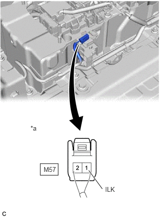
- Disconnect the M57 service plug grip (interlock switch) connector.
- Connect the cable to the negative (-) auxiliary battery terminal.
- Turn the ignition switch to ON.
- Measure the voltage according to the value(s) in the table below.
Standard Voltage
Tester Connection Condition Specified Condition M57-1 (ILK) - Body ground Ignition switch ON 11 to 14 V NOTE:Turning the ignition switch to ON with the service plug grip removed causes other DTCs to be stored. Clear the DTCs after performing this inspection.
*a Rear view of wire harness connector
(to Service Plug Grip (Interlock Switch)) - Turn the ignition switch off.
- Disconnect the cable from the negative (-) auxiliary battery terminal.
- Reconnect the M57 service plug grip (interlock switch) connector.
- Install the No. 10 HV battery shield panel.
Result
Proceed to OK NG
Result:
NG
See step 11
Result:
OK
See step 8
- Check that the service plug grip is not installed.
- CHECK SERVICE PLUG GRIP WARNING:
Be sure to wear insulated gloves.
- Remove the service plug grip.
Refer to REMOVAL [12/2019 - 10/2022] , or refer to REMOVAL [10/2022 - 11/2023]
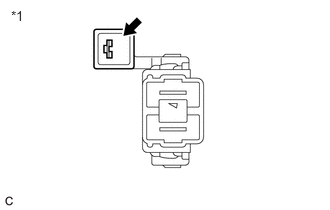
- Check the condition of the service plug grip interlock.
*1 Service Plug Grip OK
Dirt or foreign matter has not entered the connectors, and there is no evidence of contamination.
Result
Proceed to OK NG
Result:
NG
REPLACE SERVICE PLUG GRIP
Refer to REMOVAL [12/2019 - 10/2022] , or refer to REMOVAL [10/2022 - 11/2023]
Result:
OK
See step 9
- Remove the service plug grip.
- CHECK HARNESS AND CONNECTOR (SERVICE PLUG GRIP - BODY GROUND) WARNING:
Be sure to wear insulated gloves.
- Check that the service plug grip is not installed.NOTE:
After removing the service plug grip, do not turn the ignition switch to ON (READY), unless instructed by the repair information because this may cause a malfunction.
- Remove the No. 10 HV battery shield panel.
Refer to REMOVAL [12/2019 - 10/2022] , or refer to REMOVAL [10/2022 - 11/2023]
- Disconnect the M57 service plug grip (interlock switch) connector.
- Measure the resistance according to the value(s) in the table below.
Standard Resistance
Tester Connection Condition Specified Condition M57-2 (GND) - Body ground Ignition switch off Below 1 Ω *a Rear view of wire harness connector
(to Service Plug Grip (Interlock Switch)) - Reconnect the M57 service plug grip (interlock switch) connector.
- Install the No. 10 HV battery shield panel.
Result
Proceed to OK NG
Result:
NG
REPAIR OR REPLACE HARNESS OR CONNECTOR
Result:
OK
See step 10
- Check that the service plug grip is not installed.
- CHECK CONNECTOR CONNECTION CONDITION (INTERLOCK CIRCUIT)
- Check the connections of each connector.
OK
Dirt or foreign matter has not entered the connectors, and there is no evidence of contamination.
Result
Proceed to OK NG
Result:
OK
REPLACE HYBRID VEHICLE CONTROL ECU
Refer to REMOVAL [12/2019 - 10/2022] , or refer to REMOVAL [10/2022 - 11/2023]
Result:
NG
REPAIR OR REPLACE CONNECTOR
- Check the connections of each connector.
- CHECK HARNESS AND CONNECTOR (HYBRID VEHICLE CONTROL ECU - SERVICE PLUG GRIP) WARNING:
Be sure to wear insulated gloves.
- Check that the service plug grip is not installed.NOTE:
After removing the service plug grip, do not turn the ignition switch to ON (READY), unless instructed by the repair information because this may cause a malfunction.
- Disconnect the A32 hybrid vehicle control ECU connector.
- Remove the No. 10 HV battery shield panel.
Refer to REMOVAL [12/2019 - 10/2022] , or refer to REMOVAL [10/2022 - 11/2023]
- Disconnect the M57 service plug grip (interlock switch) connector.
- Measure the resistance according to the value(s) in the table below.
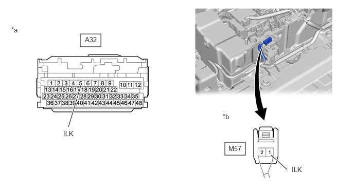
*a Front view of wire harness connector
(to Hybrid Vehicle Control ECU)*b Rear view of wire harness connector
(to Service Plug Grip (Interlock Switch))Standard Resistance
Tester Connection Condition Specified Condition A32-5 (ILK) - M57-1 (ILK) Ignition switch off Below 1 Ω - Reconnect the M57 service plug grip (interlock switch) connector.
- Install the No. 10 HV battery shield panel.
- Reconnect the A32 hybrid vehicle control ECU connector.
Result
Proceed to OK NG
Result:
OK
REPLACE HYBRID VEHICLE CONTROL ECU
Refer to REMOVAL [12/2019 - 10/2022] , or refer to REMOVAL [10/2022 - 11/2023]
Result:
NG
REPAIR OR REPLACE HARNESS OR CONNECTOR
- Check that the service plug grip is not installed.