DTC P0A1B-94: Drive Motor "A" Control Module Unexpected Operation [12/2019 - 11/2023]: Procedure
- CHECK AUXILIARY BATTERY TERMINAL (CONTACT PROBLEM)
- Check the connection of the negative (-) and positive (+) auxiliary battery terminals.
OK
The terminals are connected securely and there is no contact problem.
HINT:
If performing a simulation test, turn the ignition switch to ON and shake the wire harnesses vertically and horizontally before checking for DTCs.
Result
Proceed to OK NG
Result:
NG
See step 6
Result:
OK
See step 2
- Check the connection of the negative (-) and positive (+) auxiliary battery terminals.
- CHECK GROUND WIRE CONNECTION CONDITION
- Check the installation condition of the ground wires OA.
OK
The ground wires OA are securely installed.
HINT:
If performing a simulation test, turn the ignition switch to ON and shake the wire harnesses vertically and horizontally before checking for DTCs.
Result
Proceed to OK NG
Result:
NG
See step 7
Result:
OK
See step 3
- Check the installation condition of the ground wires OA.
- CHECK FUSE (IGCT-IG)
- Remove the IGCT-IG fuse from the No. 5 floor relay block and No. 5 floor junction block assembly.
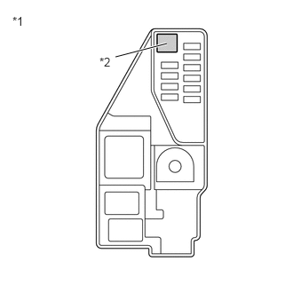
*1 No. 5 Floor Relay Block and No. 5 Floor Junction Block Assembly *2 IGCT-IG Fuse - Measure the resistance according to the value(s) in the table below.
Standard Resistance
Tester Connection Condition Specified Condition IGCT-IG fuse Always Below 1 Ω - Reinstall the IGCT-IG fuse.
Result
Proceed to OK NG
Result:
NG
See step 8
Result:
OK
See step 4
- Remove the IGCT-IG fuse from the No. 5 floor relay block and No. 5 floor junction block assembly.
- CHECK RELAY (IGCT)
- Check the IGCT relay for improper installation.
OK
The relay is installed securely.
HINT:
If performing a simulation test, turn the ignition switch to ON and gently vibrate the IGCT relay with a finger before checking for DTCs.
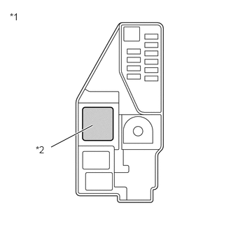
- Remove the IGCT relay from the No. 5 floor relay block and No. 5 floor junction block assembly.
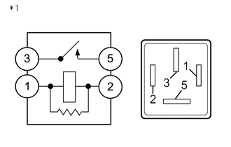
*1 No. 5 Relay Block and No. 5 Floor Junction Block Assembly *2 IGCT Relay - Measure the resistance according to the value(s) in the table below.
*1 IGCT Relay Standard Resistance
Tester Connection Condition Specified Condition 3 - 5 Auxiliary battery voltage not applied between terminals 1 and 2 10 kΩ or higher Auxiliary battery voltage applied between terminals 1 and 2 Below 1 Ω - Install the IGCT relay.
Result
Proceed to OK NG
Result:
NG
See step 9
Result:
OK
See step 5
- Check the IGCT relay for improper installation.
- CHECK DTC OUTPUT (HYBRID CONTROL)
- Check for DTCs.
HINT:
Check the DTCs that were output when the vehicle was brought to the workshop.
Powertrain > Hybrid Control > Trouble Codes
Result
Result Proceed to P0A1B-94 only is output. A DTCs except P0A1B-94 are output. B - Turn the ignition switch off.
Result:
A
REPLACE INVERTER WITH CONVERTER ASSEMBLY. Refer to REMOVAL [12/2019 - 10/2022] , or refer to REMOVAL [10/2022 - 11/2023]
Result:
B
GO TO DTC CHART (HYBRID CONTROL SYSTEM). Refer to DIAGNOSTIC TROUBLE CODE CHART [12/2019 - 09/2020] , or refer to DIAGNOSTIC TROUBLE CODE CHART [09/2020 - 10/2021] , or refer to DIAGNOSTIC TROUBLE CODE CHART [10/2021 - 11/2023]
- Check for DTCs.
- CONNECT SECURELY
Result
Proceed to NEXT Result:
NEXT
See step 10
- CONNECT SECURELY
Result
Proceed to NEXT Result:
NEXT
See step 10
- REPAIR OR REPLACE MALFUNCTIONING PARTS
Result
Proceed to NEXT Result:
NEXT
See step 10
- REPAIR OR REPLACE MALFUNCTIONING PARTS
Result
Proceed to NEXT Result:
NEXT
See step 10
- CLEAR DTC
See step 3
Result
Proceed to NEXT Result:
NEXT
See step 11
- SIMULATION TEST
- Turn the ignition switch to ON and wait for 2 minutes or more.
- Turn the ignition switch off.
Result
Proceed to NEXT
Result:
NEXT
See step 12
- CHECK DTC OUTPUT (HYBRID CONTROL)
- Check for DTCs.
Powertrain > Hybrid Control > Trouble Codes
Result
Result Proceed to No DTCs are output. A P0A1B-94 only is output. B DTCs except P0A1B-94 are output. C - Turn the ignition switch off.
Result:
A
END
Result:
B
REPLACE INVERTER WITH CONVERTER ASSEMBLY. Refer to REMOVAL [12/2019 - 10/2022] , or refer to REMOVAL [10/2022 - 11/2023]
Result:
C
GO TO DTC CHART (HYBRID CONTROL SYSTEM). Refer to DIAGNOSTIC TROUBLE CODE CHART [12/2019 - 09/2020] , or refer to DIAGNOSTIC TROUBLE CODE CHART [09/2020 - 10/2021] , or refer to DIAGNOSTIC TROUBLE CODE CHART [10/2021 - 11/2023]
- Check for DTCs.