Terminals Of Ecu [12/2019 - 10/2022]
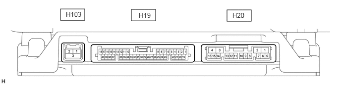
- PARKING ASSIST ECU
- Disconnect the H20 parking assist ECU connector.
- Measure the voltage and resistance according to the value(s) in the table below.
Terminal No. (Symbol) Terminal Description Condition Specified Condition H20-1 (+B) - H20-4 (GND1) Power source signal Always*1 11 to 14 V Ignition switch off*2 H20-2 (ACC) - H20-4 (GND1) ACC power source signal Ignition switch ACC 11 to 14 V Ignition switch off Below 1 V H20-3 (IG) - H20-4 (GND1) IG power source signal Ignition switch ON 11 to 14 V Ignition switch off Below 1 V H20-4 (GND1) - Body ground Ground Always Below 1 Ω - *1: for Gasoline Model
- *2: for HV Model
- Reconnect the H20 parking assist ECU connector.
- Measure the voltage, resistance and waveform according to the value(s) in the table below.
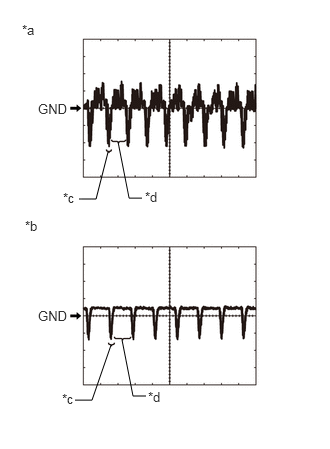
Terminal No. (Symbol) Terminal Description Condition Specified Condition H19-6 (RSW+) - H20-4 (GND1) Terminal required by law Panoramic image being displayed 0 to 2 V Panoramic image not being displayed 5.5 to 7.05 V H19-10 (LCV+) - H19-35 (LGND) Side television camera assembly LH display signal input Ignition switch ON with the camera lens of the side television camera assembly LH not covered, displaying the panoramic image Pulse generation (See waveform 1) Ignition switch ON with the camera lens of the side television camera assembly LH covered, blacking out the panoramic image Pulse generation (See waveform 2) H19-11 (SGND) - Body ground Shielded - Body ground Always Below 1 Ω H19-12 (LCB+) - H19-35 (LGND) Power source to side television camera assembly LH Ignition switch ON 5.5 to 7.05 V H19-13 (BCV-) - H20-4 (GND1) Front television camera assembly ground Always Below 1 Ω H19-14 (SGND) - Body ground Shielded - Body ground Always Below 1 Ω H19-15 (BCB+) - H19-37 (BGND) Power source to front television camera assembly Ignition switch ON 5.5 to 7.05 V H19-16 (RCV-) - H20-4 (GND1) Side television camera assembly RH ground Always Below 1 Ω H19-17 (RGND) - H20-4 (GND1) Side television camera assembly RH ground Always Below 1 Ω H19-29 (CV+) - H19-32 (CGND) Rear television camera assembly display signal input Ignition switch ON with the camera lens of the rear television camera assembly not covered, displaying the panoramic image Pulse generation (See waveform 1) Ignition switch ON with the camera lens of the rear television camera assembly covered, blacking out the panoramic image Pulse generation (See waveform 2) H19-30 (CV-) - H20-4 (GND1) Rear television camera assembly ground Always Below 1 Ω H19-31 (SGND) - Body ground Shielded - Body ground Always Below 1 Ω H19-32 (CGND) - Body ground Rear television camera assembly ground (shield) Always Below 1 Ω H19-33 (CB+) - H19-32 (CGND) Power source to rear television camera assembly Ignition switch ON 5.5 to 7.05 V H19-34 (LCV-) - H20-4 (GND1) Side television camera assembly LH ground Always Below 1 Ω H19-35 (LGND) - H20-4 (GND1) Side television camera assembly LH ground Always Below 1 Ω H19-36 (BCV+) - H19-37 (BGND) Front television camera assembly display signal input Ignition switch ON with the camera lens of the front television camera assembly not covered, displaying the panoramic image Pulse generation (See waveform 1) Ignition switch ON with the camera lens of the front television camera assembly covered, blacking out the panoramic image Pulse generation (See waveform 2) H19-37 (BGND) - H20-4 (GND1) Front television camera assembly ground Always Below 1 Ω H19-38 (RCV+) - H19-17 (RGND) Side television camera assembly RH display signal input Ignition switch ON with the camera lens of the side television camera assembly RH not covered, displaying the panoramic image Pulse generation (See waveform 1) Ignition switch ON with the camera lens of the side television camera assembly RH covered, blacking out the panoramic image Pulse generation (See waveform 2) H19-39 (SGND) - Body ground Shielded - Body ground Always Below 1 Ω H19-40 (RCB+) - H19-17 (RGND) Power source to side television camera assembly RH Ignition switch ON 5.5 to 7.05 V H20-14 (REV) - H20-4 (GND1) Reverse signal input Ignition switch ON, panoramic view monitor switch (front wide view switch) on, shift lever in R Below 1 V Ignition switch ON, panoramic view monitor switch (front wide view switch) on, shift lever except R 11 to 14 V H20-15 (BLSW) - Body ground Panoramic view monitor switch (front wide view switch) signal Ignition switch ON, panoramic view monitor switch (front wide view switch) not pushed 5.5 to 6.5 V Ignition switch ON, panoramic view monitor switch (front wide view switch) pushed Below 1 V H20-11 (CANH) CAN communication line - - H20-12 (CANL) CAN communication line - - H103-1 (GV+) Video signal (Digital) - - H103-2 (GV-) Video signal (Digital) - - H103-3 (GND) Shield ground - - *a Waveform 1 (camera lens is not covered, displaying an image) *b Waveform 2 (camera lens is covered, blacking out the screen) *c Synchronization Signal *d Video Waveform Reference (Oscilloscope waveform):
HINT:
A waterproof connector is used for the rear television camera assembly, front television camera assembly, side television camera assembly LH and side television camera assembly RH. Therefore, inspect the waveform at the parking assist ECU with the connector connected.
- Waveform 1 (camera lens is not covered, displaying an image)
Item Content Measurement terminal - H19-29 (CV+) - H19-32 (CGND)
- H19-10 (LCV+) - H19-35 (LGND)
- H19-36 (BCV+) - H19-37 (BGND)
- H19-38 (RCV+) - H19-17 (RGND)
Measurement setting 200 mV/DIV., 50 μs./DIV. Condition Panoramic view monitor system operating HINT:
- The video waveform changes according to the image sent by the rear television camera assembly, front television camera assembly, side television camera assembly LH or side television camera assembly RH.
- The video waveform is constantly output when the ignition switch is turned to ACC.
- Waveform 2 (camera lens is covered, blacking out the screen)
Item Content Measurement terminal - H19-29 (CV+) - H19-32 (CGND)
- H19-10 (LCV+) - H19-35 (LGND)
- H19-36 (BCV+) - H19-37 (BGND)
- H19-38 (RCV+) - H19-17 (RGND)
Measurement setting 200 mV/DIV., 50 μs./DIV. Condition Panoramic view monitor system operating HINT:
- The video waveform changes according to the image sent by the rear television camera assembly, front television camera assembly, side television camera assembly LH or side television camera assembly RH.
- The video waveform is constantly output when the ignition switch is turned to ACC.
- Waveform 1 (camera lens is not covered, displaying an image)
- RADIO RECEIVER ASSEMBLY
Refer to TERMINALS OF ECU [12/2019 - 10/2022]
- MULTI-DISPLAY ASSEMBLY
Refer to TERMINALS OF ECU [12/2019 - 10/2022]