DTC P0A81-11: Hybrid/EV Battery Cooling Fan 1 Circuit Short to Ground; DTC P0A81-4B: Hybrid/EV Battery Cooling Fan 1 Over Temperature; DTC P0A96-11: Hybrid/EV Battery Cooling Fan 2 Circuit Short to Ground; DTC P0A96-4B: Hybrid/EV Battery Cooling Fan 2 Over Temperature [12/2019 - 11/2023]: Procedure
- CHECK DTC OUTPUT (HYBRID CONTROL)
- Check for DTCs.
Powertrain > Hybrid Control > Trouble Codes
Result
Result Proceed to P0AFC-00 or P0AFC-96 is not output. A P0AFC-00 or P0AFC-96 is output. B - Turn the ignition switch off.
Result:
B
GO TO DTC CHART (HYBRID CONTROL SYSTEM). Refer to DIAGNOSTIC TROUBLE CODE CHART [12/2019 - 09/2020] , or refer to DIAGNOSTIC TROUBLE CODE CHART [09/2020 - 10/2021] , or refer to DIAGNOSTIC TROUBLE CODE CHART [10/2021 - 11/2023]
Result:
A
See step 2
- Check for DTCs.
- CHECK DTC
- Check the DTCs that were output when the vehicle was brought to the workshop.
Result
Result Proceed to P0A81-11 or P0A81-4B is also output. A P0A96-11 or P0A96-4B is also output. B
Result:
B
See step 29
Result:
A
See step 3
- Check the DTCs that were output when the vehicle was brought to the workshop.
- PERFORM ACTIVE TEST USING GTS (CONTROL THE HYBRID BATTERY COOLING FAN)
- Clear the DTCs and Freeze Frame Data.
Powertrain > Hybrid Control > Clear DTCs
- Select fan mode 6 in the "Control the Hybrid Battery Cooling Fan" Active Test to operate the battery cooling blower assembly (No. 0).NOTE:
If the Active Test cannot be performed, skip it and proceed to the next step to check if the fan operates and air is sucked in. In accordance with fail-safe system operation, the battery voltage sensor sends a command to operate the battery cooling blower assembly (No. 0).
Powertrain > Hybrid Control > Active Test
Tester Display Control the Hybrid Battery Cooling Fan - Check that the battery cooling blower assembly (No. 0) operates, air is sucked into the inlet duct and the operation sound is normal.
HINT:
The battery cooling blower assembly (No. 0) may not stop even when turning the cooling fan off in the "Control the Hybrid Battery Cooling Fan" Active Test. This is due to HV system control and is not a malfunction.
OK
The battery cooling blower assembly (No. 0) operates.
- Turn the ignition switch off.
Result
Proceed to OK NG
Result:
NG
See step 8
Result:
OK
See step 4
- Clear the DTCs and Freeze Frame Data.
- CHECK HARNESS AND CONNECTOR (BATTERY VOLTAGE SENSOR - BATTERY COOLING BLOWER ASSEMBLY (NO. 0)) WARNING:
Be sure to wear insulated gloves and protective goggles.
- Check that the service plug grip is not installed.NOTE:
After removing the service plug grip, do not turn the ignition switch to ON (READY), unless instructed by the repair information because this may cause a malfunction.
- Remove the HV battery junction block assembly.
Refer to REMOVAL [12/2019 - 10/2022] , or refer to REMOVAL [10/2022 - 11/2023]
- Disconnect the y1 battery voltage sensor connector.NOTE:
Before disconnecting the connector, check that it is not loose or disconnected.
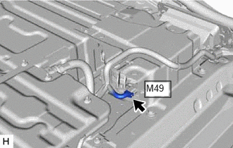
- Disconnect the M49 battery cooling blower assembly (No. 0) connector.NOTE:
Before disconnecting the connector, check that it is not loose or disconnected.
- Measure the resistance according to the value(s) in the table below.
Standard Resistance
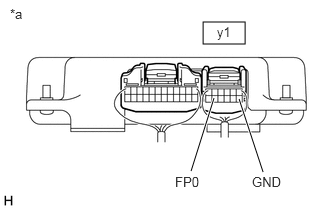
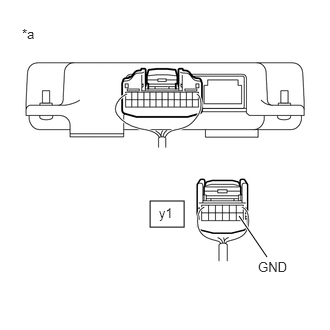
Tester Connection Condition Specified Condition y1-11 (FP0) - M49-2 (FP0) Ignition switch off Below 1 Ω y1-11 (FP0) - Body ground and other terminals Ignition switch off 10 kΩ or higher *a Rear view of wire harness connector
(to Battery Voltage Sensor)*b Front view of wire harness connector
(to Battery Cooling Blower Assembly (No. 0)) - Connect the cable to the negative (-) auxiliary battery terminal.
- Turn the ignition switch to ON.
- Measure the voltage according to the value(s) in the table below.
Standard Voltage
Tester Connection Condition Specified Condition y1-11 (FP0) - Body ground Ignition switch ON Below 1 V NOTE:- Turning the ignition switch to ON with the service plug grip removed causes other DTCs to be stored. Clear the DTCs after performing this inspection.
- If the ignition switch is turned to ON with the connectors disconnected, other DTCs will be stored. Be sure to clear the DTCs after the inspection.
HINT:
As there might be an intermittent malfunction, inspect the following items even if the measured voltage is as specified.
Check the condition of each wire harness and each connector between the battery voltage sensor connector and battery cooling blower assembly (No. 0).
- Turn the ignition switch off.
- Disconnect the cable from the negative (-) auxiliary battery terminal.
- Reconnect the M49 battery cooling blower assembly (No. 0) connector.
- Reconnect the y1 battery voltage sensor connector.
- Install the HV battery junction block assembly.
Result
Proceed to OK NG
Result:
NG
REPAIR OR REPLACE HARNESS OR CONNECTOR
Result:
OK
See step 5
- Check that the service plug grip is not installed.
- READ VALUE USING GTS (HYBRID BATTERY COOLING FAN 1 FREQUENCY) WARNING:
Be sure to wear insulated gloves.
- Check that the service plug grip is not installed.NOTE:
After removing the service plug grip, do not turn the ignition switch to ON (READY), unless instructed by the repair information because this may cause a malfunction.
- Remove the HV battery junction block assembly.
Refer to REMOVAL [12/2019 - 10/2022] , or refer to REMOVAL [10/2022 - 11/2023]
- Connect the cable to the negative (-) auxiliary battery terminal.
- Clear the DTCs and Freeze Frame Data.
Powertrain > Hybrid Control > Clear DTCs
- Select each fan mode 1 to 6 in the "Control the Hybrid Battery Cooling Fan" Active Test to operate the battery cooling blower assembly (No. 0).NOTE:
If the Active Test cannot be performed, skip it and proceed to the next step to check the frequency value. In accordance with fail-safe system operation, the battery voltage sensor sends a command to operate the battery cooling fan assembly (No. 0).
Powertrain > Hybrid Control > Active Test
Active Test Display Control the Hybrid Battery Cooling Fan Data List Display Hybrid Battery Cooling Fan 1 Frequency - While the battery cooling blower assembly (No. 0) is operating, compare the value in the Data List (Hybrid Battery Cooling Fan 1 Frequency) with the frequency value that was actually measured at the battery voltage sensor connector.
Specified Condition
Tester Connection Condition y1-11 (FP0) - y1-7 (GND) Battery cooling blower assembly (No. 0) is operating. NOTE:Turning the ignition switch to ON with the service plug grip removed causes other DTCs to be stored. Clear the DTCs after performing this inspection.
HINT:
Compare the values in each fan mode 1 to 6. If the Active Test cannot be performed, compare the values only in the current fan mode.
*a Component with harness connected
(Battery Voltage Sensor)Result
Result Proceed to Both of the values in the Data List (Hybrid Battery Cooling Fan 1 Frequency) and the actual measured value at the battery voltage sensor connector are 0 Hz. A Other than above B - Turn the ignition switch off.
- Disconnect the cable from the negative (-) auxiliary battery terminal.
- Install the HV battery junction block assembly.
Result:
B
See step 7
Result:
A
See step 6
- Check that the service plug grip is not installed.
- CHECK BATTERY VOLTAGE SENSOR WARNING:
Be sure to wear insulated gloves.
- Check that the service plug grip is not installed.NOTE:
After removing the service plug grip, do not turn the ignition switch to ON (READY), unless instructed by the repair information because this may cause a malfunction.
- Remove the rear floor silencer.
Refer to REMOVAL [12/2019 - ]
- Disconnect the M49 battery cooling blower assembly (No. 0) connector.NOTE:
Before disconnecting the connector, check that it is not loose or disconnected.
- Connect the cable to the negative (-) auxiliary battery terminal.
- Turn the ignition switch to ON.
- Measure the voltage according to the value(s) in the table below.
Standard Voltage
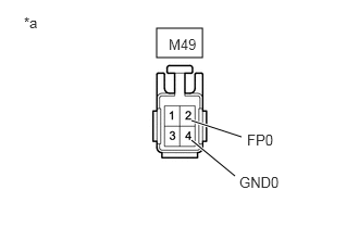
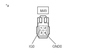
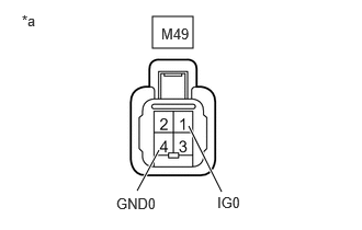
Tester Connection Condition Specified Condition M49-2 (FP0) - M49-4 (GND0) Ignition switch ON 4.5 to 5.5 V *a Front view of wire harness connector
(to Battery Cooling Blower Assembly (No. 0))NOTE:- Turning the ignition switch to ON with the service plug grip removed causes other DTCs to be stored. Clear the DTCs after performing this inspection.
- If the ignition switch is turned to ON with the connectors disconnected, other DTCs will be stored. Be sure to clear the DTCs after the inspection.
- Turn the ignition switch off.
- Disconnect the cable from the negative (-) auxiliary battery terminal.
- Reconnect the M49 battery cooling blower assembly (No. 0) connector.
- Install the rear floor silencer.
Result
Proceed to OK NG
Result:
OK
REPLACE BATTERY COOLING BLOWER ASSEMBLY (NO. 0). Refer to REMOVAL [12/2019 - ]
Result:
NG
REPLACE BATTERY VOLTAGE SENSOR. Refer to REMOVAL [12/2019 - 10/2022] , or refer to REMOVAL [10/2022 - 11/2023]
- Check that the service plug grip is not installed.
- CHECK BATTERY VOLTAGE SENSOR (FREQUENCY) WARNING:
Be sure to wear insulated gloves and protective goggles.
- Check that the service plug grip is not installed.NOTE:
After removing the service plug grip, do not turn the ignition switch to ON (READY), unless instructed by the repair information because this may cause a malfunction.
- Remove the HV battery junction block assembly.
Refer to REMOVAL [12/2019 - 10/2022] , or refer to REMOVAL [10/2022 - 11/2023]
- Connect the cable to the negative (-) auxiliary battery terminal.
- Clear the DTCs and Freeze Frame Data.
Powertrain > Hybrid Control > Clear DTCs
- Select each fan mode 1 to 6 in the "Control the Hybrid Battery Cooling Fan" Active Test to operate the battery cooling blower assembly (No. 0).NOTE:
If the Active Test cannot be performed, skip it and proceed to the next step to check the frequency value. In accordance with fail-safe system operation, the battery voltage sensor sends a command to operate the battery cooling blower assembly (No. 0).
Powertrain > Hybrid Control > Active Test
Active Test Display Control the Hybrid Battery Cooling Fan Data List Display Hybrid Battery Cooling Fan 1 Frequency - While the battery cooling blower assembly (No. 0) is operating, compare the value in the Data List (Hybrid Battery Cooling Fan 1 Frequency) with the frequency value that was actually measured at the battery voltage sensor connector.
Specified Condition
Tester Connection Condition Specified Condition y1-11 (FP0) - y1-7 (GND) Battery cooling blower assembly (No. 0) is operating. Difference between the value in the Data List (Hybrid Battery Cooling Fan 1 Frequency) and the actual measured value at the battery voltage sensor connector is 10% or less. NOTE:Turning the ignition switch to ON with the service plug grip removed causes other DTCs to be stored. Clear the DTCs after performing this inspection.
*a Component with harness connected
(Battery Voltage Sensor)HINT:
Compare the values in each fan mode 1 to 6. If the Active Test cannot be performed, compare the values only in the current fan mode.
- Turn the ignition switch off.
- Disconnect the cable from the negative (-) auxiliary battery terminal.
- Install the HV battery junction block assembly.
Result
Proceed to OK NG
Result:
OK
REPLACE BATTERY COOLING BLOWER ASSEMBLY (NO. 0). Refer to REMOVAL [12/2019 - ]
Result:
NG
REPLACE BATTERY VOLTAGE SENSOR. Refer to REMOVAL [12/2019 - 10/2022] , or refer to REMOVAL [10/2022 - 11/2023]
- Check that the service plug grip is not installed.
- CHECK FUSE (BATT FAN NO. 1)
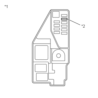
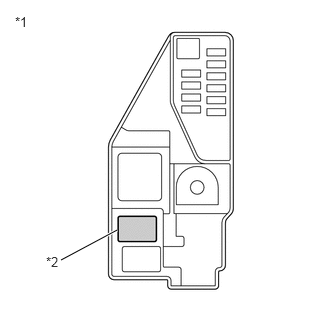
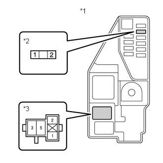
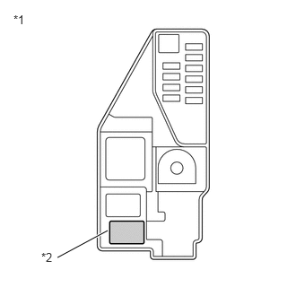
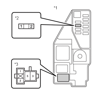
- Remove the BATT FAN NO. 1 fuse from the No. 5 floor relay block and No. 5 floor junction block assembly.
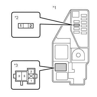
*1 No. 5 Floor Relay Block and No. 5 Floor Junction Block Assembly *2 BATT FAN NO. 1 Fuse - Measure the resistance according to the value(s) in the table below.
Standard Resistance
Tester Connection Condition Specified Condition BATT FAN NO. 1 fuse Always Below 1 Ω - Install the BATT FAN NO. 1 fuse.
Result
Proceed to OK NG
Result:
NG
See step 23
Result:
OK
See step 9
- Remove the BATT FAN NO. 1 fuse from the No. 5 floor relay block and No. 5 floor junction block assembly.
- CHECK RELAY (BATT FAN NO. 1)
- Remove the BATT FAN NO. 1 relay from the No. 5 floor relay block and No. 5 floor junction block assembly.
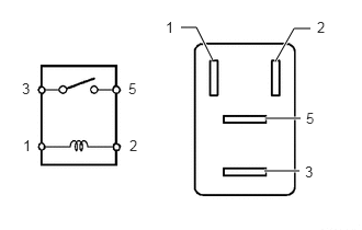
*1 No. 5 Floor Relay Block and No. 5 Floor Junction Block Assembly *2 BATT FAN NO. 1 Relay - Measure the resistance according to the value(s) in the table below.
Standard Resistance
Tester Connection Condition Specified Condition 3 - 5 Auxiliary battery voltage not applied between terminals 1 and 2 10 kΩ or higher Auxiliary battery voltage applied between terminals 1 and 2 Below 1 Ω - Install the BATT FAN NO. 1 relay.
Result
Proceed to OK NG
Result:
NG
REPLACE RELAY (BATT FAN NO. 1)
Result:
OK
See step 10
- Remove the BATT FAN NO. 1 relay from the No. 5 floor relay block and No. 5 floor junction block assembly.
- CHECK CONNECTOR CONNECTION CONDITION (FLOOR WIRE CONNECTOR)
- Check the connection condition of the battery cooling blower connector (floor wire connector) and the contact pressure of each terminal. Check the terminal for deformation, and check the connector for water ingress and foreign matter.
Refer to ELECTRONIC CIRCUIT INSPECTION PROCEDURE [12/2019 - ]
OK
- The connector is connected securely.
- The terminals are not deformed and are connected securely.
- No water or foreign matter in the connectors.
Result
Result Proceed to OK A NG (The connector is not connected securely.) B NG (The terminals are not making secure contact or are deformed, or water or foreign matter exists in the connector.) C
Result:
B
CONNECT SECURELY
Result:
C
REPAIR OR REPLACE HARNESS OR CONNECTOR
Result:
A
See step 11
- Check the connection condition of the battery cooling blower connector (floor wire connector) and the contact pressure of each terminal. Check the terminal for deformation, and check the connector for water ingress and foreign matter.
- CHECK CONNECTOR CONNECTION CONDITION (NO. 2 FLOOR WIRE CONNECTOR)
- Check the connection condition of the battery cooling blower connector (No. 2 floor wire connector) and the contact pressure of each terminal. Check the terminal for deformation, and check the connector for water ingress and foreign matter.
Refer to ELECTRONIC CIRCUIT INSPECTION PROCEDURE [12/2019 - ]
OK
- The connector is connected securely.
- The terminals are not deformed and are connected securely.
- No water or foreign matter in the connectors.
Result
Result Proceed to OK A NG (The connector is not connected securely.) B NG (The terminals are not making secure contact or are deformed, or water or foreign matter exists in the connector.) C
Result:
B
CONNECT SECURELY
Result:
C
REPAIR OR REPLACE HARNESS OR CONNECTOR
Result:
A
See step 12
- Check the connection condition of the battery cooling blower connector (No. 2 floor wire connector) and the contact pressure of each terminal. Check the terminal for deformation, and check the connector for water ingress and foreign matter.
- CHECK HARNESS AND CONNECTOR (BATT FAN NO. 1 FUSE - BATTERY COOLING BLOWER ASSEMBLY (NO. 0)) WARNING:
Be sure to wear insulated gloves.
- Check that the service plug grip is not installed.NOTE:
After removing the service plug grip, do not turn the ignition switch to ON (READY), unless instructed by the repair information because this may cause a malfunction.
- Remove the rear floor silencer.
Refer to REMOVAL [12/2019 - ]
- Disconnect the M49 battery cooling blower assembly (No. 0) connector.NOTE:
Before disconnecting the connector, check that it is not loose or disconnected.
- Connect the cable to the negative (-) auxiliary battery terminal.
- Clear the DTCs and Freeze Frame Data.
Powertrain > Hybrid Control > Clear DTCs
- Measure the voltage according to the value(s) in the table below.
Standard Voltage
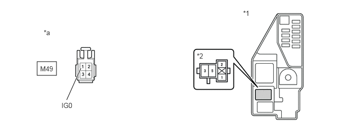
Tester Connection Condition Specified Condition M49-1 (IG0) - M49-4 (GND0) Ignition switch ON 11 to 14 V NOTE:- Turning the ignition switch to ON with the service plug grip removed causes other DTCs to be stored. Clear the DTCs after performing this inspection.
- If the ignition switch is turned to ON with the connectors disconnected, other DTCs will be stored. Be sure to clear the DTCs after the inspection.
HINT:
As there might be an intermittent malfunction, inspect the following items even if the measured voltage is as specified.
- Installation condition of fuse(s) (before removing fuse(s)) (IG circuit)
- Fuse condition (before and after removing fuse(s)) (IG circuit)
- Connection condition of connectors (IG circuit)
- Wire harness condition (IG circuit)
- Wire harness condition (GND circuit)
*a Front view of wire harness connector
(to Battery Cooling Blower Assembly (No. 0)) - Turn the ignition switch off.
- Disconnect the cable from the negative (-) auxiliary battery terminal.
- Reconnect the M49 battery cooling blower assembly (No. 0) connector.
- Install the rear floor silencer.
Result
Proceed to OK NG
Result:
NG
See step 17
Result:
OK
See step 13
- Check that the service plug grip is not installed.
- CHECK HARNESS AND CONNECTOR (BATTERY VOLTAGE SENSOR - BATTERY COOLING BLOWER ASSEMBLY (NO. 0)) WARNING:
Be sure to wear insulated gloves.
- Check that the service plug grip is not installed.NOTE:
After removing the service plug grip, do not turn the ignition switch to ON (READY), unless instructed by the repair information because this may cause a malfunction.
- Remove the HV battery junction block assembly.
Refer to REMOVAL [12/2019 - 10/2022] , or refer to REMOVAL [10/2022 - 11/2023]
- Disconnect the y1 battery voltage sensor connector.NOTE:
- Before disconnecting the connector, check that it is not loose or disconnected.
- Check that each connector between the battery voltage sensor and battery cooling blower assembly (No. 0) is not loose or disconnected.
- Disconnect the M49 battery cooling blower assembly (No. 0) connector.NOTE:
- Before disconnecting the connector, check that it is not loose or disconnected.
- Check the terminals of the connector for deformation and corrosion.
- Measure the resistance according to the value(s) in the table below.
*a Rear view of wire harness connector
(to Battery Voltage Sensor)*b Front view of wire harness connector
(to Battery Cooling Blower Assembly (No. 0))Standard Resistance
Tester Connection Condition Specified Condition y1-5 (SI0) - M49-3 (SI0) Ignition switch off Below 1 Ω M49-3 (SI0) - Body ground and other terminals Ignition switch off 10 kΩ or higher NOTE:Make sure that each connector between the battery voltage sensor and battery cooling blower assembly (No. 0) is not loose or disconnected and its terminals are not deformed or corroded.
- Connect the cable to the negative (-) auxiliary battery terminal.
- Turn the ignition switch to ON.
- Measure the voltage according to the value(s) in the table below.
Standard Voltage
Tester Connection Condition Specified Condition M49-3 (SI0) - Body ground Ignition switch ON Below 1 V NOTE:- Turning the ignition switch to ON with the service plug grip removed causes other DTCs to be stored. Clear the DTCs after performing this inspection.
- If the ignition switch is turned to ON with the connectors disconnected, other DTCs will be stored. Be sure to clear the DTCs after the inspection.
HINT:
As there might be an intermittent malfunction, inspect the following items even if the measured voltage is as specified.
Check the condition of each wire harness and each connector between the battery voltage sensor connector and battery cooling blower assembly (No. 0).
- Turn the ignition switch off.
- Disconnect the cable from the negative (-) auxiliary battery terminal.
- Reconnect the M49 battery cooling blower assembly (No. 0) connector.
- Reconnect the y1 battery voltage sensor connector.
- Install the HV battery junction block assembly.
Result
Proceed to OK NG
Result:
NG
REPAIR OR REPLACE HARNESS OR CONNECTOR
Result:
OK
See step 14
- Check that the service plug grip is not installed.
- CHECK BATTERY VOLTAGE SENSOR
- Remove the battery voltage sensor.
Refer to REMOVAL [12/2019 - 10/2022] , or refer to REMOVAL [10/2022 - 11/2023]
- Measure the resistance according to the value(s) in the table below.
*a Component without harness connected
(Battery Voltage Sensor)Standard Resistance
Tester Connection Condition Specified Condition y1-5 (SI0) - y1-7 (GND) Ignition switch off 10 kΩ or higher - Install the battery voltage sensor.
Result
Proceed to OK NG
Result:
NG
REPLACE BATTERY VOLTAGE SENSOR. Refer to REMOVAL [12/2019 - 10/2022] , or refer to REMOVAL [10/2022 - 11/2023]
Result:
OK
See step 15
- Remove the battery voltage sensor.
- CHECK BATTERY VOLTAGE SENSOR (SI0 VOLTAGE) WARNING:
Be sure to wear insulated gloves.
- Check that the service plug grip is not installed.NOTE:
After removing the service plug grip, do not turn the ignition switch to ON (READY), unless instructed by the repair information because this may cause a malfunction.
- Remove the HV battery junction block assembly.
Refer to REMOVAL [12/2019 - 10/2022] , or refer to REMOVAL [10/2022 - 11/2023]
- Connect the cable to the negative (-) auxiliary battery terminal.
- Turn the ignition switch to ON.
- Measure the voltage according to the value(s) in the table below.
Standard Voltage
Tester Connection Condition Specified Condition y1-5 (SI0) - y1-7 (GND) Ignition switch ON 4.5 to 5.5 V *a Component with harness connected
(Battery Voltage Sensor) - Turn the ignition switch off.
- Disconnect the cable from the negative (-) auxiliary battery terminal.
- Install the HV battery junction block assembly.
Result
Proceed to OK NG
Result:
NG
REPLACE BATTERY COOLING BLOWER ASSEMBLY (NO. 0). Refer to REMOVAL [12/2019 - ]
Result:
OK
See step 16
- Check that the service plug grip is not installed.
- CHECK BATTERY COOLING BLOWER ASSEMBLY (NO. 0) WARNING:
Be sure to wear insulated gloves.
- Check that the service plug grip is not installed.NOTE:
After removing the service plug grip, do not turn the ignition switch to ON (READY), unless instructed by the repair information because this may cause a malfunction.
- Remove the HV battery junction block assembly.
Refer to REMOVAL [12/2019 - 10/2022] , or refer to REMOVAL [10/2022 - 11/2023]
- Connect the cable to the negative (-) auxiliary battery terminal.
- Clear the DTCs and Freeze Frame Data.
Powertrain > Hybrid Control > Clear DTCs
- Select each fan mode 1 to 6 in the "Control the Hybrid Battery Cooling Fan" Active Test to operate the battery cooling blower assembly (No. 0).NOTE:
If the Active Test cannot be performed, skip it and proceed to the next step to check the waveform. In accordance with fail-safe system operation, the battery voltage sensor sends a command to operate the battery cooling blower assembly (No. 0).
Powertrain > Hybrid Control > Active Test
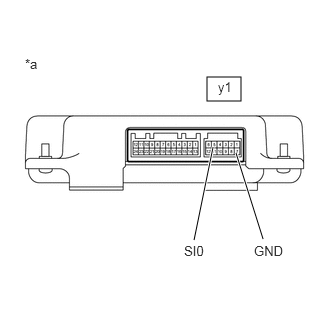
Tester Display Control the Hybrid Battery Cooling Fan - Connect an oscilloscope to the y1 battery voltage sensor connector and check the waveform.
Item Content Tester Connection y1-5 (SI0) - y1-7 (GND) Equipment Setting 10 V/DIV., 1 ms./DIV. Condition Ignition switch ON, during Active Test HINT:
- Perform this inspection with the battery voltage sensor connector connected.
- The wave length will vary with the operating speed of the battery cooling blower assembly (No. 0).
*a Component with harness connected
(Battery Voltage Sensor)Result
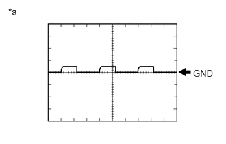
Result Proceed to Normal (The pulse output of waveform 1) A No pulse generation B - Turn the ignition switch off.
- Disconnect the cable from the negative (-) auxiliary battery terminal.
*a Waveform 1 - Install the HV battery junction block assembly.
Result:
A
REPLACE BATTERY COOLING BLOWER ASSEMBLY (NO. 0). Refer to REMOVAL [12/2019 - ]
Result:
B
REPLACE BATTERY VOLTAGE SENSOR. Refer to REMOVAL [12/2019 - 10/2022] , or refer to REMOVAL [10/2022 - 11/2023]
- Check that the service plug grip is not installed.
- CHECK HARNESS AND CONNECTOR (BATTERY COOLING BLOWER ASSEMBLY (NO. 0) - BODY GROUND) WARNING:
Be sure to wear insulated gloves.
- Check that the service plug grip is not installed.NOTE:
After removing the service plug grip, do not turn the ignition switch to ON (READY), unless instructed by the repair information because this may cause a malfunction.
- Remove the rear floor silencer.
Refer to REMOVAL [12/2019 - ]
- Disconnect the M49 battery cooling blower assembly (No. 0) connector.NOTE:
Before disconnecting the connector, check that it is not loose or disconnected.
- Measure the resistance according to the value(s) in the table below.
Standard Resistance
Tester Connection Condition Specified Condition M49-4 (GND0) - Body ground Ignition switch off Below 1 Ω *a Front view of wire harness connector
(to Battery Cooling Blower Assembly (No. 0)) - Reconnect the M49 battery cooling blower assembly (No. 0) connector.
- Install the rear floor silencer.
Result
Proceed to OK NG
Result:
NG
REPAIR OR REPLACE HARNESS OR CONNECTOR
Result:
OK
See step 18
- Check that the service plug grip is not installed.
- CHECK HARNESS AND CONNECTOR (BATTERY VOLTAGE SENSOR - BODY GROUND) WARNING:
Be sure to wear insulated gloves.
- Check that the service plug grip is not installed.NOTE:
After removing the service plug grip, do not turn the ignition switch to ON (READY), unless instructed by the repair information because this may cause a malfunction.
- Remove the HV battery junction block assembly.
Refer to REMOVAL [12/2019 - 10/2022] , or refer to REMOVAL [10/2022 - 11/2023]
- Disconnect the y1 battery voltage sensor connector.NOTE:
Before disconnecting the connector, check that it is not loose or disconnected.
- Measure the resistance according to the value(s) in the table below.
Standard Resistance
Tester Connection Condition Specified Condition y1-7 (GND) - Body ground Ignition switch off Below 1 Ω *a Rear view of wire harness connector
(to Battery Voltage Sensor) - Reconnect the y1 battery voltage sensor connector.
- Install the HV battery junction block assembly.
Result
Proceed to OK NG
Result:
NG
REPAIR OR REPLACE HARNESS OR CONNECTOR
Result:
OK
See step 19
- Check that the service plug grip is not installed.
- CHECK HARNESS AND CONNECTOR (IGCT NO. 2 FUSE - BATT FAN NO. 1 RELAY)
- Remove the IGCT NO. 2 fuse, BATT FAN NO. 1 relay and BATT FAN NO. 2 relay from the No. 5 floor relay block and No. 5 floor junction block assembly.
- Measure the resistance according to the value(s) in the table below.
*1 No. 5 Floor Relay Block and No. 5 Floor Junction Block Assembly *2 IGCT NO. 2 Fuse Holder *3 BATT FAN NO. 1 Relay Holder Standard Resistance
Tester Connection Condition Specified Condition 2 (IGCT NO. 2 fuse holder) - 1 (BATT FAN NO. 1 relay holder) Ignition switch off Below 1 Ω NOTE:When taking a measurement with a tester, do not apply excessive force to the tester probe to avoid damaging the holder.
- Install the IGCT NO. 2 fuse, BATT FAN NO. 1 relay and BATT FAN NO. 2 relay.
Result
Proceed to OK NG
Result:
NG
REPAIR OR REPLACE HARNESS OR CONNECTOR
Result:
OK
See step 20
- CHECK HARNESS AND CONNECTOR (BATT FAN NO. 1 RELAY - AUXILIARY BATTERY)
- Remove the BATT FAN NO. 1 relay from the No. 5 floor relay block and No. 5 floor junction block assembly.
- Measure the voltage according to the value(s) in the table below.
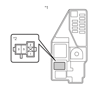
*1 No. 5 Floor Relay Block and No. 5 Floor Junction Block Assembly *2 BATT FAN NO. 1 Relay Holder Standard Voltage
Tester Connection Condition Specified Condition 3 (BATT FAN NO. 1 relay holder) - Body ground Ignition switch off 11 to 14 V NOTE:When taking a measurement with a tester, do not apply excessive force to the tester probe to avoid damaging the holder.
- Install the BATT FAN NO. 1 relay.
Result
Proceed to OK NG
Result:
NG
REPAIR OR REPLACE HARNESS OR CONNECTOR
Result:
OK
See step 21
- CHECK HARNESS AND CONNECTOR (BATT FAN NO. 1 RELAY - BODY GROUND)
- Remove the BATT FAN NO. 1 relay from the No. 5 floor relay block and No. 5 floor junction block assembly.
- Measure the resistance according to the value(s) in the table below.
*1 No. 5 Floor Relay Block and No. 5 Floor Junction Block Assembly *2 BATT FAN NO. 1 Relay Holder Standard Resistance
Tester Connection Condition Specified Condition 2 (BATT FAN NO. 1 relay holder) - Body ground Ignition switch off Below 1 Ω NOTE:When taking a measurement with a tester, do not apply excessive force to the tester probe to avoid damaging the holder.
- Install the BATT FAN NO. 1 relay.
Result
Proceed to OK NG
Result:
NG
REPAIR OR REPLACE HARNESS OR CONNECTOR
Result:
OK
See step 22
- CHECK HARNESS AND CONNECTOR (BATT FAN NO. 1 RELAY - BATTERY COOLING BLOWER ASSEMBLY (NO. 0)) WARNING:
Be sure to wear insulated gloves.
- Check that the service plug grip is not installed.NOTE:
After removing the service plug grip, do not turn the ignition switch to ON (READY), unless instructed by the repair information because this may cause a malfunction.
- Remove the BATT FAN NO. 1 relay from the No. 5 floor relay block and No. 5 floor junction block assembly.NOTE:
Check the terminals of the relay for deformation and corrosion.
- Remove the rear floor silencer.
Refer to REMOVAL [12/2019 - ]
- Disconnect the M49 battery cooling blower assembly (No. 0) connector.NOTE:
- Check that each connector between the BATT FAN NO. 1 relay and battery cooling blower assembly (No. 0) is not loose or disconnected.
- Before disconnecting the connector, check that it is not loose or disconnected.
- Measure the resistance according to the value(s) in the table below.
*1 No. 5 Floor Relay Block and No. 5 Floor Junction Block Assembly *2 BATT FAN NO. 1 Relay Holder *a Front view of wire harness connector
(to Battery Cooling Blower Assembly (No. 0))- - Standard Resistance
Tester Connection Condition Specified Condition 5 (BATT FAN NO. 1 relay holder) - M49-1 (IG0) Ignition switch off Below 1 Ω NOTE:- When taking a measurement with a tester, do not apply excessive force to the tester probe to avoid damaging the holder.
- Check that each connector between the BATT FAN NO. 1 relay and battery cooling blower assembly (No. 0) is not loose or disconnected.
- Reconnect the M49 battery cooling blower assembly (No. 0) connector.
- Install the rear floor silencer.
- Install the BATT FAN NO. 1 relay.
Result
Proceed to OK NG
Result:
OK
REPLACE BATTERY VOLTAGE SENSOR. Refer to REMOVAL [12/2019 - 10/2022] , or refer to REMOVAL [10/2022 - 11/2023]
Result:
NG
REPAIR OR REPLACE HARNESS OR CONNECTOR
- Check that the service plug grip is not installed.
- CHECK HARNESS AND CONNECTOR (BATT FAN NO. 1 FUSE - BATT FAN NO. 1 RELAY)
- Remove the BATT FAN NO. 1 fuse and BATT FAN NO. 1 relay from the No. 5 floor relay block and No. 5 floor junction block assembly.
- Measure the resistance according to the value(s) in the table below.
Standard Resistance
Tester Connection Condition Specified Condition 2 (BATT FAN NO. 1 fuse holder) - Terminals other than 3 (BATT FAN NO. 1 relay holder) and body ground Ignition switch off 10 kΩ or higher NOTE:When taking a measurement with a tester, do not apply excessive force to the tester probe to avoid damaging the holder.
*1 No. 5 Floor Relay Block and No. 5 Floor Junction Block Assembly *2 BATT FAN NO. 1 Fuse Holder *3 BATT FAN NO. 1 Relay Holder - Install the BATT FAN NO. 1 fuse and BATT FAN NO. 1 relay.
Result
Proceed to OK NG
Result:
NG
See step 26
Result:
OK
See step 24
- CHECK HARNESS AND CONNECTOR (BATT FAN NO. 1 RELAY - BATTERY COOLING BLOWER ASSEMBLY (NO. 0)) WARNING:
Be sure to wear insulated gloves.
- Check that the service plug grip is not installed.NOTE:
After removing the service plug grip, do not turn the ignition switch to ON (READY), unless instructed by the repair information because this may cause a malfunction.
- Remove the BATT FAN NO. 1 relay from the No. 5 floor relay block and No. 5 floor junction block assembly.
- Remove the rear floor silencer.
Refer to REMOVAL [12/2019 - ]
- Disconnect the M49 battery cooling blower assembly (No. 0) connector.NOTE:
Before disconnecting the connector, check that it is not loose or disconnected.
- Measure the resistance according to the value(s) in the table below.
*1 No. 5 Floor Relay Block and No. 5 Floor Junction Block Assembly *2 BATT FAN NO. 1 Relay Holder *a Front view of wire harness connector
(to Battery Cooling Blower Assembly (No. 0))- - Standard Resistance
Tester Connection Condition Specified Condition 5 (BATT FAN NO. 1 relay holder) - M49-1 (IG0) Ignition switch off 10 kΩ or higher NOTE:When taking a measurement with a tester, do not apply excessive force to the tester probe to avoid damaging the holder.
- Reconnect the M49 battery cooling blower assembly (No. 0) connector.
- Install the rear floor silencer.
- Install the BATT FAN NO. 1 relay.
Result
Proceed to OK NG
Result:
NG
See step 27
Result:
OK
See step 25
- Check that the service plug grip is not installed.
- CHECK BATTERY COOLING BLOWER ASSEMBLY (NO. 0) WARNING:
Be sure to wear insulated gloves.
- Check that the service plug grip is not installed.NOTE:
After removing the service plug grip, do not turn the ignition switch to ON (READY), unless instructed by the repair information because this may cause a malfunction.
- Remove the rear floor silencer.
Refer to REMOVAL [12/2019 - ]
- Disconnect the M49 battery cooling blower assembly (No. 0) connector.NOTE:
Before disconnecting the connector, check that it is not loose or disconnected.
- Measure the resistance according to the value(s) in the table below.
Standard Resistance
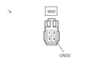
Tester Connection Condition Specified Condition M49-1 (IG0) - M49-4 (GND0) and Body ground Ignition switch off 10 kΩ or higher *a Component without harness connected
(Battery Cooling Blower Assembly (No. 0))NOTE:When taking a measurement with a tester, do not apply excessive force to the tester probe to avoid damaging the holder.
- Reconnect the M49 battery cooling blower assembly (No. 0) connector.
- Install the rear floor silencer.
Result
Proceed to OK NG
Result:
OK
REPLACE FUSE (BATT FAN NO. 1)
Result:
NG
See step 28
- Check that the service plug grip is not installed.
- REPAIR OR REPLACE HARNESS OR CONNECTOR
Result
Proceed to NEXT Result:
NEXT
REPLACE FUSE (BATT FAN NO. 1)
- REPAIR OR REPLACE HARNESS OR CONNECTOR
Result
Proceed to NEXT Result:
NEXT
REPLACE FUSE (BATT FAN NO. 1)
- REPLACE BATTERY COOLING BLOWER ASSEMBLY (NO. 0)
Refer to REMOVAL [12/2019 - ]
Result
Proceed to NEXT Result:
NEXT
REPLACE FUSE (BATT FAN NO. 1)
- PERFORM ACTIVE TEST USING GTS (CONTROL THE HYBRID BATTERY COOLING FAN)
- Connect the GTS to the DLC3.
- Clear the DTCs and Freeze Frame Data.
Powertrain > Hybrid Control > Clear DTCs
- Select fan mode 6 in the "Control the Hybrid Battery Cooling Fan" Active Test to operate the battery cooling blower assembly (No. 1).NOTE:
If the Active Test cannot be performed, skip it and proceed to the next step to check if the fan operates and air is sucked in. In accordance with fail-safe system operation, the battery voltage sensor sends a command to operate the battery cooling blower assembly (No. 1).
Powertrain > Hybrid Control > Active Test
Tester Display Control the Hybrid Battery Cooling Fan - Check that the battery cooling blower assembly (No. 1) operates, air is sucked into the inlet duct and the operation sound is normal.
HINT:
The battery cooling blower assembly (No. 1) may not stop even when turning the cooling fan off in the "Control the Hybrid Battery Cooling Fan" Active Test. This is due to HV system control and is not a malfunction.
OK
The battery cooling blower assembly (No. 1) operates.
- Turn the ignition switch off.
Result
Proceed to OK NG
Result:
NG
See step 34
Result:
OK
See step 30
- CHECK HARNESS AND CONNECTOR (BATTERY VOLTAGE SENSOR - BATTERY COOLING BLOWER ASSEMBLY (NO. 1)) WARNING:
Be sure to wear insulated gloves and protective goggles.
- Check that the service plug grip is not installed.NOTE:
After removing the service plug grip, do not turn the ignition switch to ON (READY), unless instructed by the repair information because this may cause a malfunction.
- Remove the HV battery junction block assembly.
Refer to REMOVAL [12/2019 - 10/2022] , or refer to REMOVAL [10/2022 - 11/2023]
- Disconnect the y1 battery voltage sensor connector.NOTE:
Before disconnecting the connector, check that it is not loose or disconnected.
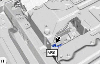
- Disconnect the M50 battery cooling blower assembly (No. 1) connector.NOTE:
Before disconnecting the connector, check that it is not loose or disconnected.
- Measure the resistance according to the value(s) in the table below.
Standard Resistance
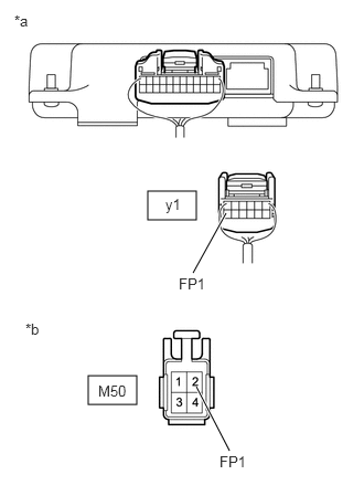
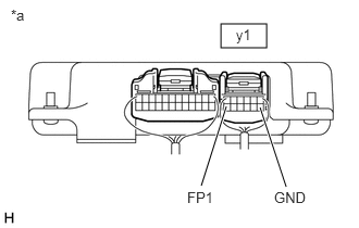
Tester Connection Condition Specified Condition y1-12 (FP1) - M50-2 (FP1) Ignition switch off Below 1 Ω y1-12 (FP1) - Body ground and other terminals Ignition switch off 10 kΩ or higher *a Rear view of wire harness connector
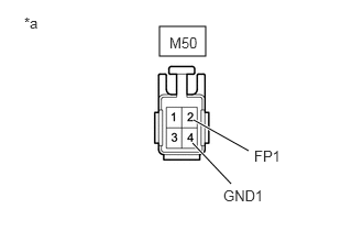
(to Battery Voltage Sensor)*b Front view of wire harness connector
(to Battery Cooling Blower Assembly (No. 1)) - Connect the cable to the negative (-) auxiliary battery terminal.
- Turn the ignition switch to ON.
- Measure the voltage according to the value(s) in the table below.
Standard Voltage
Tester Connection Condition Specified Condition y1-12 (FP1) - Body ground Ignition switch ON Below 1 V NOTE:- Turning the ignition switch to ON with the service plug grip removed causes other DTCs to be stored. Clear the DTCs after performing this inspection.
- If the ignition switch is turned to ON with the connectors disconnected, other DTCs will be stored. Be sure to clear the DTCs after the inspection.
HINT:
As there might be an intermittent malfunction, inspect the following items even if the measured voltage is as specified.
Check the condition of each wire harness and each connector between the battery voltage sensor connector and battery cooling blower assembly (No. 1).
- Turn the ignition switch off.
- Disconnect the cable from the negative (-) auxiliary battery terminal.
- Reconnect the M50 battery cooling blower assembly (No. 1) connector.
- Reconnect the y1 battery voltage sensor connector.
- Install the HV battery junction block assembly.
Result
Proceed to OK NG
Result:
NG
REPAIR OR REPLACE HARNESS OR CONNECTOR
Result:
OK
See step 31
- Check that the service plug grip is not installed.
- READ VALUE USING GTS (HYBRID/EV BATTERY COOLING FAN 2 FREQUENCY) WARNING:
Be sure to wear insulated gloves.
- Check that the service plug grip is not installed.NOTE:
After removing the service plug grip, do not turn the ignition switch to ON (READY), unless instructed by the repair information because this may cause a malfunction.
- Remove the HV battery junction block assembly.
Refer to REMOVAL [12/2019 - 10/2022] , or refer to REMOVAL [10/2022 - 11/2023]
- Connect the cable to the negative (-) auxiliary battery terminal.
- Clear the DTCs and Freeze Frame Data.
Powertrain > Hybrid Control > Clear DTCs
- Select each fan mode 1 to 6 in the "Control the Hybrid Battery Cooling Fan" Active Test to operate the battery cooling blower assembly (No. 1).NOTE:
If the Active Test cannot be performed, skip it and proceed to the next step to check the frequency value. In accordance with fail-safe system operation, the battery voltage sensor sends a command to operate the battery cooling fan assembly (No. 1).
Powertrain > Hybrid Control > Active Test
Active Test Display Control the Hybrid Battery Cooling Fan Data List Display Hybrid/EV Battery Cooling Fan 2 Frequency - While the battery cooling blower assembly (No. 1) is operating, compare the value in the Data List (Hybrid/EV Battery Cooling Fan 2 Frequency) with the frequency value that was actually measured at the battery voltage sensor connector.
Specified Condition
Tester Connection Condition y1-12 (FP1) - y1-7 (GND) Battery cooling blower assembly (No. 1) is operating. NOTE:Turning the ignition switch to ON with the service plug grip removed causes other DTCs to be stored. Clear the DTCs after performing this inspection.
HINT:
Compare the values in each fan mode 1 to 6. If the Active Test cannot be performed, compare the values only in the current fan mode.
*a Component with harness connected
(Battery Voltage Sensor)Result
Result Proceed to Both of the values in the Data List (Hybrid/EV Battery Cooling Fan 2 Frequency) and the actual measured value at the battery voltage sensor connector are 0 Hz. A Other than above B - Turn the ignition switch off.
- Disconnect the cable from the negative (-) auxiliary battery terminal.
- Install the HV battery junction block assembly.
Result:
B
See step 33
Result:
A
See step 32
- Check that the service plug grip is not installed.
- CHECK BATTERY VOLTAGE SENSOR WARNING:
Be sure to wear insulated gloves.
- Check that the service plug grip is not installed.NOTE:
After removing the service plug grip, do not turn the ignition switch to ON (READY), unless instructed by the repair information because this may cause a malfunction.
- Remove the rear floor silencer.
Refer to REMOVAL [12/2019 - ]
- Disconnect the M50 battery cooling blower assembly (No. 1) connector.NOTE:
Before disconnecting the connector, check that it is not loose or disconnected.
- Connect the cable to the negative (-) auxiliary battery terminal.
- Turn the ignition switch to ON.
- Measure the voltage according to the value(s) in the table below.
Standard Voltage
Tester Connection Condition Specified Condition M50-2 (FP1) - M50-4 (GND1) Ignition switch ON 4.5 to 5.5 V *a Front view of wire harness connector
(to Battery Cooling Blower Assembly (No. 1))NOTE:- Turning the ignition switch to ON with the service plug grip removed causes other DTCs to be stored. Clear the DTCs after performing this inspection.
- If the ignition switch is turned to ON with the connectors disconnected, other DTCs will be stored. Be sure to clear the DTCs after the inspection.
- Turn the ignition switch off.
- Disconnect the cable from the negative (-) auxiliary battery terminal.
- Reconnect the M50 battery cooling blower assembly (No. 1) connector.
- Install the rear floor silencer.
Result
Proceed to OK NG
Result:
OK
REPLACE BATTERY COOLING BLOWER ASSEMBLY (NO. 1). Refer to REMOVAL [12/2019 - ]
Result:
NG
REPLACE BATTERY VOLTAGE SENSOR. Refer to REMOVAL [12/2019 - 10/2022] , or refer to REMOVAL [10/2022 - 11/2023]
- Check that the service plug grip is not installed.
- CHECK BATTERY VOLTAGE SENSOR (FREQUENCY) WARNING:
Be sure to wear insulated gloves and protective goggles.
- Check that the service plug grip is not installed.NOTE:
After removing the service plug grip, do not turn the ignition switch to ON (READY), unless instructed by the repair information because this may cause a malfunction.
- Remove the HV battery junction block assembly.
Refer to REMOVAL [12/2019 - 10/2022] , or refer to REMOVAL [10/2022 - 11/2023]
- Connect the cable to the negative (-) auxiliary battery terminal.
- Clear the DTCs and Freeze Frame Data.
Powertrain > Hybrid Control > Clear DTCs
- Select each fan mode 1 to 6 in the "Control the Hybrid Battery Cooling Fan" Active Test to operate the battery cooling blower assembly (No. 1).NOTE:
If the Active Test cannot be performed, skip it and proceed to the next step to check the frequency value. In accordance with fail-safe system operation, the battery voltage sensor sends a command to operate the battery cooling blower assembly (No. 1).
Powertrain > Hybrid Control > Active Test
Active Test Display Control the Hybrid Battery Cooling Fan Data List Display Hybrid/EV Battery Cooling Fan 2 Frequency - While the battery cooling blower assembly (No. 1) is operating, compare the value in the Data List (Hybrid/EV Battery Cooling Fan 2 Frequency) with the frequency value that was actually measured at the battery voltage sensor connector.
Specified Condition
Tester Connection Condition Specified Condition y1-12 (FP1) - y1-7 (GND) Battery cooling blower assembly (No. 1) is operating. Difference between the value in the Data List (Hybrid/EV Battery Cooling Fan 2 Frequency) and the actual measured value at the battery voltage sensor connector is 10% or less. NOTE:Turning the ignition switch to ON with the service plug grip removed causes other DTCs to be stored. Clear the DTCs after performing this inspection.
*a Component with harness connected
(Battery Voltage Sensor)HINT:
Compare the values in each fan mode 1 to 6. If the Active Test cannot be performed, compare the values only in the current fan mode.
- Turn the ignition switch off.
- Disconnect the cable from the negative (-) auxiliary battery terminal.
- Install the HV battery junction block assembly.
Result
Proceed to OK NG
Result:
OK
REPLACE BATTERY COOLING BLOWER ASSEMBLY (NO. 1). Refer to REMOVAL [12/2019 - ]
Result:
NG
REPLACE BATTERY VOLTAGE SENSOR. Refer to REMOVAL [12/2019 - 10/2022] , or refer to REMOVAL [10/2022 - 11/2023]
- Check that the service plug grip is not installed.
- CHECK FUSE (BATT FAN NO. 2)
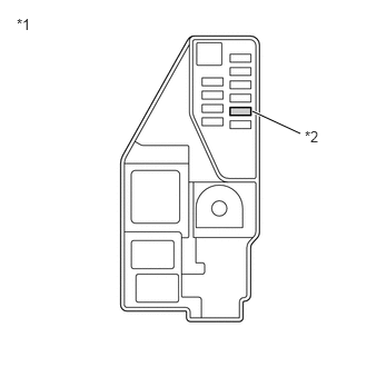
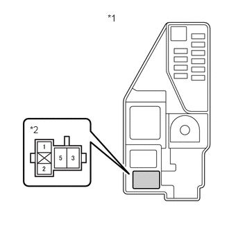
- Remove the BATT FAN NO. 2 fuse from the No. 5 floor relay block and No. 5 floor junction block assembly.
*1 No. 5 Floor Relay Block and No. 5 Floor Junction Block Assembly *2 BATT FAN NO. 2 Fuse - Measure the resistance of the BATT FAN NO. 2 fuse.
Standard Resistance
Tester Connection Condition Specified Condition BATT FAN NO. 2 fuse Ignition switch off Below 1 Ω - Install the BATT FAN NO. 2 fuse.
Result
Proceed to OK NG
Result:
NG
See step 49
Result:
OK
See step 35
- Remove the BATT FAN NO. 2 fuse from the No. 5 floor relay block and No. 5 floor junction block assembly.
- CHECK RELAY (BATT FAN NO. 2)
- Remove the BATT FAN NO. 2 relay from the No. 5 floor relay block and No. 5 floor junction block assembly.
*1 No. 5 Floor Relay Block and No. 5 Floor Junction Block Assembly *2 BATT FAN NO. 2 Relay - Measure the resistance according to the value(s) in the table below.
Standard Resistance
Tester Connection Condition Specified Condition 3 - 5 Auxiliary battery voltage not applied between terminals 1 and 2 10 kΩ or higher Auxiliary battery voltage applied between terminals 1 and 2 Below 1 Ω - Install the BATT FAN NO. 2 relay.
Result
Proceed to OK NG
Result:
NG
REPLACE RELAY (BATT FAN NO. 2)
Result:
OK
See step 36
- Remove the BATT FAN NO. 2 relay from the No. 5 floor relay block and No. 5 floor junction block assembly.
- CHECK CONNECTOR CONNECTION CONDITION (FLOOR WIRE CONNECTOR)
- Check the connection condition of the battery cooling blower connector (floor wire connector) and the contact pressure of each terminal. Check the terminal for deformation, and check the connector for water ingress and foreign matter.
Refer to ELECTRONIC CIRCUIT INSPECTION PROCEDURE [12/2019 - ]
OK
- The connector is connected securely.
- The terminals are not deformed and are connected securely.
- No water or foreign matter in the connectors.
Result
Result Proceed to OK A NG (The connector is not connected securely.) B NG (The terminals are not making secure contact or are deformed, or water or foreign matter exists in the connector.) C
Result:
B
CONNECT SECURELY
Result:
C
REPAIR OR REPLACE HARNESS OR CONNECTOR
Result:
A
See step 37
- Check the connection condition of the battery cooling blower connector (floor wire connector) and the contact pressure of each terminal. Check the terminal for deformation, and check the connector for water ingress and foreign matter.
- CHECK CONNECTOR CONNECTION CONDITION (NO. 2 FLOOR WIRE CONNECTOR)
- Check the connection condition of the battery cooling blower connector (No. 2 floor wire connector) and the contact pressure of each terminal. Check the terminal for deformation, and check the connector for water ingress and foreign matter.
Refer to ELECTRONIC CIRCUIT INSPECTION PROCEDURE [12/2019 - ]
OK
- The connector is connected securely.
- The terminals are not deformed and are connected securely.
- No water or foreign matter in the connectors.
Result
Result Proceed to OK A NG (The connector is not connected securely.) B NG (The terminals are not making secure contact or are deformed, or water or foreign matter exists in the connector.) C
Result:
B
CONNECT SECURELY
Result:
C
REPAIR OR REPLACE HARNESS OR CONNECTOR
Result:
A
See step 38
- Check the connection condition of the battery cooling blower connector (No. 2 floor wire connector) and the contact pressure of each terminal. Check the terminal for deformation, and check the connector for water ingress and foreign matter.
- CHECK HARNESS AND CONNECTOR (BATT FAN NO. 2 FUSE - BATTERY COOLING BLOWER ASSEMBLY (NO. 1)) WARNING:
Be sure to wear insulated gloves.
- Check that the service plug grip is not installed.NOTE:
After removing the service plug grip, do not turn the ignition switch to ON (READY), unless instructed by the repair information because this may cause a malfunction.
- Remove the rear floor silencer.
Refer to REMOVAL [12/2019 - ]
- Disconnect the M50 battery cooling blower assembly (No. 1) connector.NOTE:
Before disconnecting the connector, check that it is not loose or disconnected.
- Connect the cable to the negative (-) auxiliary battery terminal.
- Clear the DTCs and Freeze Frame Data.
Powertrain > Hybrid Control > Clear DTCs
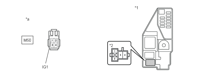
- Measure the voltage according to the value(s) in the table below.
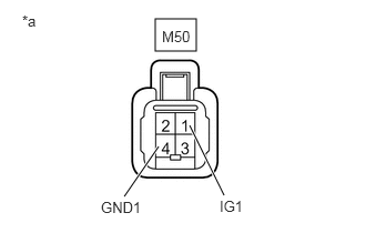
Standard Voltage
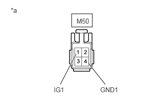
Tester Connection Condition Specified Condition M50-1 (IG1) - M50-4 (GND1) Ignition switch ON 11 to 14 V NOTE:- Turning the ignition switch to ON with the service plug grip removed causes other DTCs to be stored. Clear the DTCs after performing this inspection.
- If the ignition switch is turned to ON with the connectors disconnected, other DTCs will be stored. Be sure to clear the DTCs after the inspection.
HINT:
As there might be an intermittent malfunction, inspect the following items even if the measured voltage is as specified.
- Installation condition of fuse(s) (before removing fuse(s)) (IG circuit)
- Fuse condition (before and after removing fuse(s)) (IG circuit)
- Connection condition of connectors (IG circuit)
- Wire harness condition (IG circuit)
- Wire harness condition (GND circuit)
*a Front view of wire harness connector
(to Battery Cooling Blower Assembly (No. 1)) - Turn the ignition switch off.
- Disconnect the cable from the negative (-) auxiliary battery terminal.
- Reconnect the M50 battery cooling blower assembly (No. 1) connector.
- Install the rear floor silencer.
Result
Proceed to OK NG
Result:
NG
See step 43
Result:
OK
See step 39
- Check that the service plug grip is not installed.
- CHECK HARNESS AND CONNECTOR (BATTERY VOLTAGE SENSOR - BATTERY COOLING BLOWER ASSEMBLY (NO. 1)) WARNING:
Be sure to wear insulated gloves.
- Check that the service plug grip is not installed.NOTE:
After removing the service plug grip, do not turn the ignition switch to ON (READY), unless instructed by the repair information because this may cause a malfunction.
- Remove the HV battery junction block assembly.
Refer to REMOVAL [12/2019 - 10/2022] , or refer to REMOVAL [10/2022 - 11/2023]
- Disconnect the y1 battery voltage sensor connector.NOTE:
- Before disconnecting the connector, check that it is not loose or disconnected.
- Check that each connector between the battery voltage sensor and battery cooling blower assembly (No. 1) is not loose or disconnected.
- Disconnect the M50 battery cooling blower assembly (No. 1) connector.NOTE:
- Before disconnecting the connector, check that it is not loose or disconnected.
- Check the terminals of the connector for deformation and corrosion.
- Measure the resistance according to the value(s) in the table below.
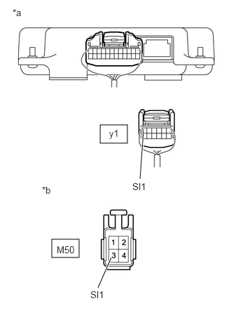
*a Rear view of wire harness connector
(to Battery Voltage Sensor)*b Front view of wire harness connector
(to Battery Cooling Blower Assembly (No. 1))Standard Resistance
Tester Connection Condition Specified Condition y1-6 (SI1) - M50-3 (SI1) Ignition switch off Below 1 Ω M50-3 (SI1) - Body ground and other terminals Ignition switch off 10 kΩ or higher NOTE:Make sure that each connector between the battery voltage sensor and battery cooling blower assembly (No. 1) is not loose or disconnected and its terminals are not deformed or corroded.
- Connect the cable to the negative (-) auxiliary battery terminal.
- Turn the ignition switch to ON.
- Measure the voltage according to the value(s) in the table below.
Standard Voltage
Tester Connection Condition Specified Condition M50-3 (SI1) - Body ground Ignition switch ON Below 1 V NOTE:- Turning the ignition switch to ON with the service plug grip removed causes other DTCs to be stored. Clear the DTCs after performing this inspection.
- If the ignition switch is turned to ON with the connectors disconnected, other DTCs will be stored. Be sure to clear the DTCs after the inspection.
HINT:
As there might be an intermittent malfunction, inspect the following items even if the measured voltage is as specified.
Check the condition of each wire harness and each connector between the battery voltage sensor connector and battery cooling blower assembly (No. 1).
- Turn the ignition switch off.
- Disconnect the cable from the negative (-) auxiliary battery terminal.
- Reconnect the M50 battery cooling blower assembly (No. 1) connector.
- Reconnect the y1 battery voltage sensor connector.
- Install the HV battery junction block assembly.
Result
Proceed to OK NG
Result:
NG
REPAIR OR REPLACE HARNESS OR CONNECTOR
Result:
OK
See step 40
- Check that the service plug grip is not installed.
- CHECK BATTERY VOLTAGE SENSOR
- Remove the battery voltage sensor.
Refer to REMOVAL [12/2019 - 10/2022] , or refer to REMOVAL [10/2022 - 11/2023]
- Measure the resistance according to the value(s) in the table below.
Standard Resistance
Tester Connection Condition Specified Condition y1-6 (SI1) - y1-7 (GND) Ignition switch off 10 kΩ or higher *a Component without harness connected
(Battery Voltage Sensor) - Install the battery voltage sensor.
Result
Proceed to OK NG
Result:
NG
REPLACE BATTERY VOLTAGE SENSOR. Refer to REMOVAL [12/2019 - 10/2022] , or refer to REMOVAL [10/2022 - 11/2023]
Result:
OK
See step 41
- Remove the battery voltage sensor.
- CHECK BATTERY VOLTAGE SENSOR (SI1 VOLTAGE) WARNING:
Be sure to wear insulated gloves.
- Check that the service plug grip is not installed.NOTE:
After removing the service plug grip, do not turn the ignition switch to ON (READY), unless instructed by the repair information because this may cause a malfunction.
- Remove the HV battery junction block assembly.
Refer to REMOVAL [12/2019 - 10/2022] , or refer to REMOVAL [10/2022 - 11/2023]
- Connect the cable to the negative (-) auxiliary battery terminal.
- Turn the ignition switch to ON.
- Measure the voltage according to the value(s) in the table below.
Standard Voltage
Tester Connection Condition Specified Condition y1-6 (SI1) - y1-7 (GND) Ignition switch ON 4.5 to 5.5 V *a Component with harness connected
(Battery Voltage Sensor) - Turn the ignition switch off.
- Disconnect the cable from the negative (-) auxiliary battery terminal.
- Install the HV battery junction block assembly.
Result
Proceed to OK NG
Result:
NG
REPLACE BATTERY COOLING BLOWER ASSEMBLY (NO. 1). Refer to REMOVAL [12/2019 - ]
Result:
OK
See step 42
- Check that the service plug grip is not installed.
- CHECK BATTERY COOLING BLOWER ASSEMBLY (NO. 1) WARNING:
Be sure to wear insulated gloves.
- Check that the service plug grip is not installed.NOTE:
After removing the service plug grip, do not turn the ignition switch to ON (READY), unless instructed by the repair information because this may cause a malfunction.
- Remove the HV battery junction block assembly.
Refer to REMOVAL [12/2019 - 10/2022] , or refer to REMOVAL [10/2022 - 11/2023]
- Connect the cable to the negative (-) auxiliary battery terminal.
- Clear the DTCs and Freeze Frame Data.
Powertrain > Hybrid Control > Clear DTCs
- Select each fan mode 1 to 6 in the "Control the Hybrid Battery Cooling Fan" Active Test to operate the battery cooling blower assembly (No. 1).NOTE:
If the Active Test cannot be performed, skip it and proceed to the next step to check the waveform. In accordance with fail-safe system operation, the battery voltage sensor sends a command to operate the battery cooling blower assembly (No. 1).
Powertrain > Hybrid Control > Active Test
Tester Display Control the Hybrid Battery Cooling Fan - Connect an oscilloscope to the y1 battery voltage sensor connector and check the waveform.
Item Content Tester Connection y1-6 (SI1) - y1-7 (GND) Equipment Setting 10 V/DIV., 1 ms./DIV. Condition Ignition switch ON, during Active Test HINT:
- Perform this inspection with the battery voltage sensor connector connected.
- The wave length will vary with the operating speed of the battery cooling blower assembly (No. 1).
*a Component with harness connected
(Battery Voltage Sensor)Result
Result Proceed to Normal (The pulse output of waveform 1) A No pulse generation B - Turn the ignition switch off.
- Disconnect the cable from the negative (-) auxiliary battery terminal.
*a Waveform 1 - Install the HV battery junction block assembly.
Result:
A
REPLACE BATTERY COOLING BLOWER ASSEMBLY (NO. 1). Refer to REMOVAL [12/2019 - ]
Result:
B
REPLACE BATTERY VOLTAGE SENSOR. Refer to REMOVAL [12/2019 - 10/2022] , or refer to REMOVAL [10/2022 - 11/2023]
- Check that the service plug grip is not installed.
- CHECK HARNESS AND CONNECTOR (BATTERY COOLING BLOWER ASSEMBLY (NO. 1) - BODY GROUND) WARNING:
Be sure to wear insulated gloves.
- Check that the service plug grip is not installed.NOTE:
After removing the service plug grip, do not turn the ignition switch to ON (READY), unless instructed by the repair information because this may cause a malfunction.
- Remove the rear floor silencer.
Refer to REMOVAL [12/2019 - ]
- Disconnect the M50 battery cooling blower assembly (No. 1) connector.NOTE:
Before disconnecting the connector, check that it is not loose or disconnected.
- Measure the resistance according to the value(s) in the table below.
Standard Resistance
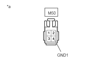
Tester Connection Condition Specified Condition M50-4 (GND1) - Body ground Ignition switch off Below 1 Ω *a Front view of wire harness connector
(to Battery Cooling Blower Assembly (No. 1)) - Reconnect the M50 battery cooling blower assembly (No. 1) connector.
- Install the rear floor silencer.
Result
Proceed to OK NG
Result:
NG
REPAIR OR REPLACE HARNESS OR CONNECTOR
Result:
OK
See step 44
- Check that the service plug grip is not installed.
- CHECK HARNESS AND CONNECTOR (BATTERY VOLTAGE SENSOR - BODY GROUND) WARNING:
Be sure to wear insulated gloves.
- Check that the service plug grip is not installed.NOTE:
After removing the service plug grip, do not turn the ignition switch to ON (READY), unless instructed by the repair information because this may cause a malfunction.
- Remove the HV battery junction block assembly.
Refer to REMOVAL [12/2019 - 10/2022] , or refer to REMOVAL [10/2022 - 11/2023]
- Disconnect the y1 battery voltage sensor connector.NOTE:
Before disconnecting the connector, check that it is not loose or disconnected.
- Measure the resistance according to the value(s) in the table below.
Standard Resistance
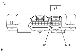
Tester Connection Condition Specified Condition y1-7 (GND) - Body ground Ignition switch off Below 1 Ω *a Rear view of wire harness connector
(to Battery Voltage Sensor) - Reconnect the y1 battery voltage sensor connector.
- Install the HV battery junction block assembly.
Result
Proceed to OK NG
Result:
NG
REPAIR OR REPLACE HARNESS OR CONNECTOR
Result:
OK
See step 45
- Check that the service plug grip is not installed.
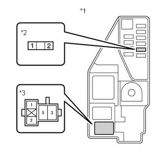
- CHECK HARNESS AND CONNECTOR (IGCT NO. 2 FUSE - BATT FAN NO. 2 RELAY)
- Remove the IGCT NO. 2 fuse, BATT FAN NO. 1 relay and BATT FAN NO. 2 relay from the No. 5 floor relay block and No. 5 floor junction block assembly.
- Measure the resistance according to the value(s) in the table below.
*1 No. 5 Floor Relay Block and No. 5 Floor Junction Block Assembly *2 IGCT NO. 2 Fuse Holder *3 BATT FAN NO. 2 Relay Holder Standard Resistance
Tester Connection Condition Specified Condition 2 (IGCT NO. 2 fuse holder) - 1 (BATT FAN NO. 2 relay holder) Ignition switch off Below 1 Ω NOTE:When taking a measurement with a tester, do not apply excessive force to the tester probe to avoid damaging the holder.
- Install the IGCT NO. 2 fuse, BATT FAN NO. 1 relay and BATT FAN NO. 2 relay.
Result
Proceed to OK NG
Result:
NG
REPAIR OR REPLACE HARNESS OR CONNECTOR
Result:
OK
See step 46
- CHECK HARNESS AND CONNECTOR (BATT FAN NO. 2 RELAY - AUXILIARY BATTERY)
- Remove the BATT FAN NO. 2 relay from the No. 5 floor relay block and No. 5 floor junction block assembly.
- Measure the voltage according to the value(s) in the table below.
*1 No. 5 Floor Relay Block and No. 5 Floor Junction Block Assembly *2 BATT FAN NO. 2 Relay Holder Standard Voltage
Tester Connection Condition Specified Condition 3 (BATT FAN NO. 2 relay holder) - Body ground Ignition switch ON 11 to 14 V NOTE:When taking a measurement with a tester, do not apply excessive force to the tester probe to avoid damaging the holder.
- Install the BATT FAN NO. 2 relay.
Result
Proceed to OK NG
Result:
NG
REPAIR OR REPLACE HARNESS OR CONNECTOR
Result:
OK
See step 47
- CHECK HARNESS AND CONNECTOR (BATT FAN NO. 2 RELAY - BODY GROUND)
- Remove the BATT FAN NO. 2 relay from the No. 5 floor relay block and No. 5 floor junction block assembly.
- Measure the resistance according to the value(s) in the table below.
*1 No. 5 Floor Relay Block and No. 5 Floor Junction Block Assembly *2 BATT FAN NO. 2 Relay Holder Standard Resistance
Tester Connection Condition Specified Condition 2 (BATT FAN NO. 2 relay holder) - Body ground Ignition switch off Below 1 Ω NOTE:When taking a measurement with a tester, do not apply excessive force to the tester probe to avoid damaging the holder.
- Install the BATT FAN NO. 2 relay.
Result
Proceed to OK NG
Result:
NG
REPAIR OR REPLACE HARNESS OR CONNECTOR
Result:
OK
See step 48
- CHECK HARNESS AND CONNECTOR (BATT FAN NO. 2 RELAY - BATTERY COOLING BLOWER ASSEMBLY (NO. 1)) WARNING:
Be sure to wear insulated gloves.
- Check that the service plug grip is not installed.NOTE:
After removing the service plug grip, do not turn the ignition switch to ON (READY), unless instructed by the repair information because this may cause a malfunction.
- Remove the BATT FAN NO. 2 relay from the No. 5 floor relay block and No. 5 floor junction block assembly.NOTE:
Check the terminals of the relay for deformation and corrosion.
- Remove the rear floor silencer.
Refer to REMOVAL [12/2019 - ]
- Disconnect the M50 battery cooling blower assembly (No. 1) connector.NOTE:
- Check that each connector between the BATT FAN NO. 2 relay and battery cooling blower assembly (No. 1) is not loose or disconnected.
- Before disconnecting the connector, check that it is not loose or disconnected.
- Measure the resistance according to the value(s) in the table below.
*1 No. 5 Floor Relay Block and No. 5 Floor Junction Block Assembly *2 BATT FAN NO. 2 Relay Holder *a Front view of wire harness connector
(to Battery Cooling Blower Assembly (No. 1))- - Standard Resistance
Tester Connection Condition Specified Condition 5 (BATT FAN NO. 2 relay holder) - M50-1 (IG1) Ignition switch off Below 1 Ω NOTE:- When taking a measurement with a tester, do not apply excessive force to the tester probe to avoid damaging the holder.
- Check that each connector between the BATT FAN NO. 2 relay and battery cooling blower assembly (No. 1) is not loose or disconnected.
- Reconnect the M50 battery cooling blower assembly (No. 1) connector.
- Install the rear floor silencer.
- Install the BATT FAN NO. 2 relay.
Result
Proceed to OK NG
Result:
OK
REPLACE BATTERY VOLTAGE SENSOR. Refer to REMOVAL [12/2019 - 10/2022] , or refer to REMOVAL [10/2022 - 11/2023]
Result:
NG
REPAIR OR REPLACE HARNESS OR CONNECTOR
- Check that the service plug grip is not installed.
- CHECK HARNESS AND CONNECTOR (BATT FAN NO. 2 FUSE - BATT FAN NO. 2 RELAY)
- Remove the BATT FAN NO. 2 fuse and BATT FAN NO. 2 relay from the No. 5 floor relay block and No. 5 floor junction block assembly.
- Measure the resistance according to the value(s) in the table below.
Standard Resistance
Tester Connection Condition Specified Condition 2 (BATT FAN NO. 2 fuse holder) - Terminals other than 3 (BATT FAN NO. 2 relay holder) and body ground Ignition switch off 10 kΩ or higher NOTE:When taking a measurement with a tester, do not apply excessive force to the tester probe to avoid damaging the holder.
*1 No. 5 Floor Relay Block and No. 5 Floor Junction Block Assembly *2 BATT FAN NO. 2 Fuse Holder *3 BATT FAN NO. 2 Relay Holder - Install the BATT FAN NO. 2 fuse and BATT FAN NO. 2 relay.
Result
Proceed to OK NG
Result:
NG
See step 52
Result:
OK
See step 50
- CHECK HARNESS AND CONNECTOR (BATT FAN NO. 2 RELAY - BATTERY COOLING BLOWER ASSEMBLY (NO. 1)) WARNING:
Be sure to wear insulated gloves.
- Check that the service plug grip is not installed.NOTE:
After removing the service plug grip, do not turn the ignition switch to ON (READY), unless instructed by the repair information because this may cause a malfunction.
- Remove the BATT FAN NO. 2 relay from the No. 5 floor relay block and No. 5 floor junction block assembly.
- Remove the rear floor silencer.
Refer to REMOVAL [12/2019 - ]
- Disconnect the M50 battery cooling blower assembly (No. 1) connector.NOTE:
Before disconnecting the connector, check that it is not loose or disconnected.
- Measure the resistance according to the value(s) in the table below.
*1 No. 5 Floor Relay Block and No. 5 Floor Junction Block Assembly *2 BATT FAN NO. 2 Relay Holder *a Front view of wire harness connector
(to Battery Cooling Blower Assembly (No. 1))- - Standard Resistance
Tester Connection Condition Specified Condition 5 (BATT FAN NO. 2 relay holder) - M50-1 (IG1) Ignition switch off 10 kΩ or higher NOTE:When taking a measurement with a tester, do not apply excessive force to the tester probe to avoid damaging the holder.
- Reconnect the M50 battery cooling blower assembly (No. 1) connector.
- Install the rear floor silencer.
- Install the BATT FAN NO. 2 relay.
Result
Proceed to OK NG
Result:
NG
See step 53
Result:
OK
See step 51
- Check that the service plug grip is not installed.
- CHECK BATTERY COOLING BLOWER ASSEMBLY (NO. 1) WARNING:
Be sure to wear insulated gloves.
- Check that the service plug grip is not installed.NOTE:
After removing the service plug grip, do not turn the ignition switch to ON (READY), unless instructed by the repair information because this may cause a malfunction.
- Remove the rear floor silencer.
Refer to REMOVAL [12/2019 - ]
- Disconnect the M50 battery cooling blower assembly (No. 1) connector.NOTE:
Before disconnecting the connector, check that it is not loose or disconnected.
- Measure the resistance according to the value(s) in the table below.
Standard Resistance
Tester Connection Condition Specified Condition M50-1 (IG1) - M50-4 (GND1) and Body ground Ignition switch off 10 kΩ or higher *a Component without harness connected
(Battery Cooling Blower Assembly (No. 1))NOTE:When taking a measurement with a tester, do not apply excessive force to the tester probe to avoid damaging the holder.
- Reconnect the M50 battery cooling blower assembly (No. 1) connector.
- Install the rear floor silencer.
Result
Proceed to OK NG
Result:
OK
REPLACE FUSE (BATT FAN NO. 2)
Result:
NG
See step 54
- Check that the service plug grip is not installed.
- REPAIR OR REPLACE HARNESS OR CONNECTOR
Result
Proceed to NEXT Result:
NEXT
REPLACE FUSE (BATT FAN NO. 2)
- REPAIR OR REPLACE HARNESS OR CONNECTOR
Result
Proceed to NEXT Result:
NEXT
REPLACE FUSE (BATT FAN NO. 2)
- REPLACE BATTERY COOLING BLOWER ASSEMBLY (NO. 1)
Refer to REMOVAL [12/2019 - ]
Result
Proceed to NEXT Result:
NEXT
REPLACE FUSE (BATT FAN NO. 2)