DTC P0A81-96: Hybrid/EV Battery Cooling Fan 1 Component Internal Failure; DTC P0A81-98: Hybrid/EV Battery Cooling Fan 1 Component or System Over Temperature; DTC P0A96-96: Hybrid/EV Battery Cooling Fan 2 Component Internal Failure; DTC P0A96-98: Hybrid/EV Battery Cooling Fan 2 Component or System Over Temperature [12/2019 - 11/2023]: Procedure
- CHECK DTC OUTPUT (HYBRID CONTROL)
- Check for DTCs.
Powertrain > Hybrid Control > Trouble Codes
Result
Result Proceed to P0AFC-00, P0AFC-96 or P308A-12 is not output. A P0AFC-00, P0AFC-96 or P308A-12 is output. B - Turn the ignition switch off.
Result:
B
GO TO DTC CHART (HYBRID CONTROL SYSTEM). Refer to DIAGNOSTIC TROUBLE CODE CHART [12/2019 - 09/2020] , or refer to DIAGNOSTIC TROUBLE CODE CHART [09/2020 - 10/2021] , or refer to DIAGNOSTIC TROUBLE CODE CHART [10/2021 - 11/2023]
Result:
A
See step 2
- Check for DTCs.
- CHECK DTC
- Check the DTCs that were output when the vehicle was brought to the workshop.
Result
Result Proceed to P0A81-96 or P0A81-98 is also output. A P0A96-96 or P0A96-98 is also output. B
Result:
B
See step 10
Result:
A
See step 3
- Check the DTCs that were output when the vehicle was brought to the workshop.
- CHECK DUCT AND BLOWER WARNING:
Be sure to wear insulated gloves.
- Check that the service plug grip is not installed.NOTE:
After removing the service plug grip, do not turn the ignition switch to ON (READY), unless instructed by the repair information because this may cause a malfunction.
- Remove the rear floor silencer.
Refer to REMOVAL [12/2019 - ]
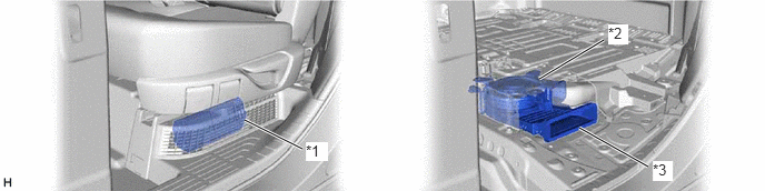
- Check that the No. 2 HV battery intake filter, battery cooling blower assembly (No. 0) and No. 1 hybrid battery intake duct are not disconnected, damaged, or clogged with foreign matter.
*1 No. 2 HV Battery Intake Filter *2 Battery Cooling Blower Assembly (No. 0) *3 No. 1 Hybrid Battery Intake Duct - - OK
The No. 2 HV battery intake filter, No. 1 hybrid battery intake duct and battery cooling blower assembly (No. 0) are not disconnected, damaged, or clogged with foreign matter.
- Install the rear floor silencer.
Result
Proceed to OK NG
Result:
NG
CORRECT THE PROBLEM
Result:
OK
See step 4
- Check that the service plug grip is not installed.
- CHECK HARNESS AND CONNECTOR (BATTERY VOLTAGE SENSOR - BATTERY COOLING BLOWER ASSEMBLY (NO. 0))
See step 4
Result
Proceed to OK NG Result:
NG
REPAIR OR REPLACE HARNESS OR CONNECTOR
Result:
OK
See step 5
- CHECK HARNESS AND CONNECTOR (BATTERY VOLTAGE SENSOR - BATTERY COOLING BLOWER ASSEMBLY (NO. 0))
See step 13
Result
Proceed to OK NG Result:
NG
REPAIR OR REPLACE HARNESS OR CONNECTOR
Result:
OK
See step 6
- CHECK BATTERY VOLTAGE SENSOR (GROUND SHORT CHECK)
- Remove the battery voltage sensor.
Refer to REMOVAL [12/2019 - 10/2022] , or refer to REMOVAL [10/2022 - 11/2023]
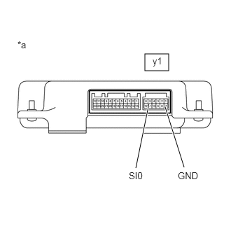
- Measure the resistance according to the value(s) in the table below.
Standard Resistance
Tester Connection Condition Specified Condition y1-5 (SI0) - y1-7 (GND) Ignition switch off 10 kΩ or higher *a Component without harness connected
(Battery Voltage Sensor) - Install the battery voltage sensor.
Result
Proceed to OK NG
Result:
NG
REPLACE BATTERY VOLTAGE SENSOR. Refer to REMOVAL [12/2019 - 10/2022] , or refer to REMOVAL [10/2022 - 11/2023]
Result:
OK
See step 7
- Remove the battery voltage sensor.
- READ VALUE USING GTS (HYBRID BATTERY COOLING FAN 1 FREQUENCY)
See step 5
Result
Result Proceed to Both of the values in the Data List (Hybrid Battery Cooling Fan 1 Frequency) and the actual measured value at the battery voltage sensor connector are 0 Hz. A Other than above B Result:
B
See step 9
Result:
A
See step 8
- CHECK BATTERY VOLTAGE SENSOR
See step 6
Result
Proceed to OK NG Result:
OK
REPLACE BATTERY COOLING BLOWER ASSEMBLY (NO. 0). Refer to REMOVAL [12/2019 - ]
Result:
NG
REPLACE BATTERY VOLTAGE SENSOR. Refer to REMOVAL [12/2019 - 10/2022] , or refer to REMOVAL [10/2022 - 11/2023]
- CHECK BATTERY VOLTAGE SENSOR (FREQUENCY)
See step 7
Result
Proceed to OK NG Result:
OK
REPLACE BATTERY COOLING BLOWER ASSEMBLY (NO. 0). Refer to REMOVAL [12/2019 - ]
Result:
NG
REPLACE BATTERY VOLTAGE SENSOR. Refer to REMOVAL [12/2019 - 10/2022] , or refer to REMOVAL [10/2022 - 11/2023]
- CHECK DUCT AND BLOWER WARNING:
Be sure to wear insulated gloves.
- Check that the service plug grip is not installed.NOTE:
After removing the service plug grip, do not turn the ignition switch to ON (READY), unless instructed by the repair information because this may cause a malfunction.
- Remove the rear floor silencer.
Refer to REMOVAL [12/2019 - ]
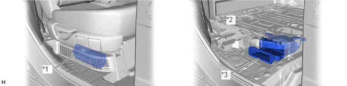
- Check that the No. 2 HV battery intake filter, battery cooling blower assembly (No. 1) and No. 1 hybrid battery intake duct are not disconnected, damaged, or clogged with foreign matter.
*1 No. 2 HV Battery Intake Filter *2 Battery Cooling Blower Assembly (No. 1) *3 No. 1 Hybrid Battery Intake Duct - - OK
The No. 2 HV battery intake filter, No. 1 hybrid battery intake duct and battery cooling blower assembly (No. 1) are not disconnected, damaged, or clogged with foreign matter.
- Install the rear floor silencer.
Result
Proceed to OK NG
Result:
NG
CORRECT THE PROBLEM
Result:
OK
See step 11
- Check that the service plug grip is not installed.
- CHECK HARNESS AND CONNECTOR (BATTERY VOLTAGE SENSOR - BATTERY COOLING BLOWER ASSEMBLY (NO. 1))
See step 30
Result
Proceed to OK NG Result:
NG
REPAIR OR REPLACE HARNESS OR CONNECTOR
Result:
OK
See step 12
- CHECK HARNESS AND CONNECTOR (BATTERY VOLTAGE SENSOR - BATTERY COOLING BLOWER ASSEMBLY (NO. 1))
See step 39
Result
Proceed to OK NG Result:
NG
REPAIR OR REPLACE HARNESS OR CONNECTOR
Result:
OK
See step 13
- CHECK BATTERY VOLTAGE SENSOR (GROUND SHORT CHECK)
- Remove the battery voltage sensor.
Refer to REMOVAL [12/2019 - 10/2022] , or refer to REMOVAL [10/2022 - 11/2023]
- Measure the resistance according to the value(s) in the table below.
Standard Resistance
Tester Connection Condition Specified Condition y1-6 (SI1) - y1-7 (GND) Ignition switch off 10 kΩ or higher *a Component without harness connected
(Battery Voltage Sensor) - Install the battery voltage sensor.
Result
Proceed to OK NG
Result:
NG
REPLACE BATTERY VOLTAGE SENSOR. Refer to REMOVAL [12/2019 - 10/2022] , or refer to REMOVAL [10/2022 - 11/2023]
Result:
OK
See step 14
- Remove the battery voltage sensor.
- READ VALUE USING GTS (HYBRID/EV BATTERY COOLING FAN 2 FREQUENCY)
See step 31
Result
Result Proceed to Both of the values in the Data List (Hybrid/EV Battery Cooling Fan 2 Frequency) and the actual measured value at the battery voltage sensor connector are 0 Hz. A Other than above B Result:
B
See step 16
Result:
A
See step 15
- CHECK BATTERY VOLTAGE SENSOR
See step 32
Result
Proceed to OK NG Result:
OK
REPLACE BATTERY COOLING BLOWER ASSEMBLY (NO. 1). Refer to REMOVAL [12/2019 - ]
Result:
NG
REPLACE BATTERY VOLTAGE SENSOR. Refer to REMOVAL [12/2019 - 10/2022] , or refer to REMOVAL [10/2022 - 11/2023]
- CHECK BATTERY VOLTAGE SENSOR (FREQUENCY)
See step 33
Result
Proceed to OK NG Result:
OK
REPLACE BATTERY COOLING BLOWER ASSEMBLY (NO. 1). Refer to REMOVAL [12/2019 - ]
Result:
NG
REPLACE BATTERY VOLTAGE SENSOR. Refer to REMOVAL [12/2019 - 10/2022] , or refer to REMOVAL [10/2022 - 11/2023]