Inspection [12/2019 - ]: Procedure
WARNING: This page is about a different variant/trim than selected.
- INSPECT FUEL PRESSURE SENSOR
- Check the fuel pressure sensor output voltage.
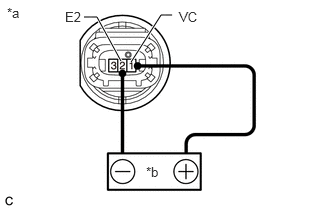
- Apply 5 V between terminals 1 (VC) and 2 (E2).NOTE:
- Be careful when connecting the leads as the fuel pressure sensor may be damaged if the leads are connected to the wrong terminals.
- Do not apply more than 6 V to terminals 1 (VC) or 2 (E2).
HINT:
If a stable power supply is not available, connect 4 nickel-metal hydride batteries (1.2 V each) or equivalent in series.
*a Component without harness connected
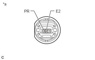
(Fuel Pressure Sensor)*b Voltage Applied between Terminals - Measure the voltage according to the value(s) in the table below.
Standard Voltage
Tester Connection Condition Specified Condition 3 (PR) - 2 (E2) Pressure not applied to fuel pressure sensor Approximately 0.4 to 0.6 V* *: The output voltage changes depending on the voltage applied to the terminals.
If the result is not as specified, replace the fuel pressure sensor.
*a Component without harness connected
(Fuel Pressure Sensor)
- Apply 5 V between terminals 1 (VC) and 2 (E2).
- Check the fuel pressure sensor output voltage.