DTC C1621: Back Camera Power Supply Failure [12/2019 - 10/2022]: Procedure
- CHECK HARNESS AND CONNECTOR (RADIO AND DISPLAY RECEIVER ASSEMBLY - REAR TELEVISION CAMERA ASSEMBLY)
- Disconnect the H2 radio and display receiver assembly connector.
- Disconnect the W15 rear television camera assembly connector.
- Measure the resistance according to the value(s) in the table below.
Standard Resistance
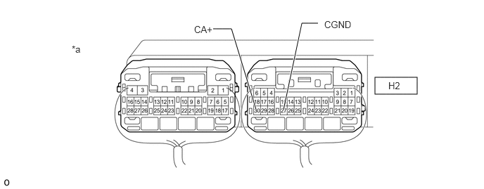
Tester Connection Condition Specified Condition H2-30 (CA+) - W15-6 (CB+) Always Below 1 Ω H2-27 (CGND) - W15-5 (CGND) Always Below 1 Ω H2-30 (CA+) or W15-6 (CB+) - Body ground Always 10 kΩ or higher H2-27 (CGND) or W15-5 (CGND) - Body ground Always 10 kΩ or higher Result
Proceed to OK NG
Result:
NG
REPAIR OR REPLACE HARNESS OR CONNECTOR
Result:
OK
See step 2
- INSPECT RADIO AND DISPLAY RECEIVER ASSEMBLY
- Disconnect the W15 rear television camera assembly connector.
*a Component with harness connected
(Radio and Display Receiver Assembly)- - - Measure the resistance according to the value(s) in the table below.
Standard Resistance
Tester Connection Condition Specified Condition H2-27 (CGND) - Body ground Always Below 1 Ω - Measure the voltage according to the value(s) in the table below.
Standard Voltage
Tester Connection Switch Condition Specified Condition H2-30 (CA+) - H2-27 (CGND) Ignition switch ACC 5.5 to 7.05 V H2-30 (CA+) - H2-27 (CGND) Ignition switch off Below 1 V Result
Proceed to OK NG
Result:
OK
REPLACE REAR TELEVISION CAMERA ASSEMBLY. Refer to REMOVAL [12/2019 - 11/2023]
Result:
NG
REPLACE RADIO AND DISPLAY RECEIVER ASSEMBLY. Refer to REMOVAL [12/2019 - 10/2022]
- Disconnect the W15 rear television camera assembly connector.