Installation [12/2019 - ]: Procedure
WARNING: This page is about a different variant/trim than selected.
- INSTALL LEAK DETECTION PUMP SUB-ASSEMBLY
HINT:
Only perform this procedure when replacement of the leak detection pump sub-assembly is necessary.
- INSTALL CANISTER (CHARCOAL CANISTER ASSEMBLY)
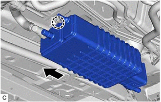
- Install the charcoal canister outlet guide to the vehicle body.
- Engage the claw to install the canister (charcoal canister assembly) to the vehicle body as shown in the illustration.
- Engage the charcoal canister outlet guide to connect the canister (charcoal canister assembly).
- Install the 2 bolts.
Torque: 8.0 N.m (82 kgf/cm, 71 in.lbf)
- Connect the fuel emission hose to the canister (charcoal canister assembly) and slide the clip to secure it.
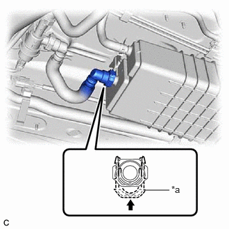
- Push the fuel tank vent hose sub-assembly onto the canister (charcoal canister assembly) and push in the retainer to engage the lock claws.NOTE:
- Check that there are no scratches or foreign matter around the connecting parts of the tube connector and pipe (canister (charcoal canister assembly)) before performing this work.
- After connecting the fuel tank vent hose sub-assembly, check that the fuel tank vent hose sub-assembly is securely connected by pulling on the tube connector.
*a Retainer 
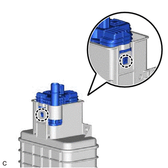
Push in - Connect the leak detection pump sub-assembly connector.
- Push in the No. 7 fuel tank breather tube to the pipe (leak detection pump sub-assembly) until the No. 7 fuel tank breather tube makes a "click" sound.NOTE:
- Check that there are no scratches or foreign matter around the connecting parts of the tube connector and pipe (leak detection pump sub-assembly) before performing this work.
- After connecting the No. 7 fuel tank breather tube, check that the No. 7 fuel tank breather tube is securely connected by pulling on the tube connector.
- INSTALL FRONT FLOOR COVER LH
Refer to PROCEDURE - Step 20 [12/2019 - 11/2023] , or refer to PROCEDURE - Step 20 [11/2023 - ]