Disassembly [10/2022 - 11/2023]: Procedure
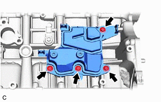
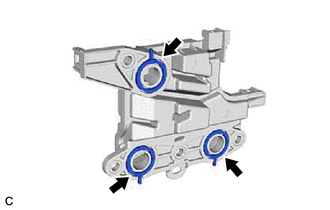
- REMOVE NO. 1 VENTILATION CASE
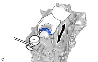
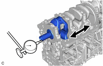
- INSPECT CONNECTING ROD THRUST CLEARANCE
- Using a dial indicator, measure the thrust clearance while moving the connecting rod sub-assembly back and forth.
Standard Thrust Clearance
0.16 to 0.51 mm (0.00630 to 0.0201 in.)
Maximum Thrust Clearance
0.512 mm (0.0202 in.)
HINT:
If the thrust clearance is more than the maximum, replace the connecting rod. If necessary, replace the crankshaft.
- Using a dial indicator, measure the thrust clearance while moving the connecting rod sub-assembly back and forth.
- INSPECT CONNECTING ROD OIL CLEARANCE
HINT:
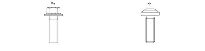
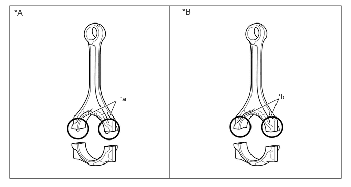
There are two types of connecting rod sub-assemblies; cracking connecting rods and other than cracking connecting rods.
*A except Cracking Connecting Rod *B Cracking Connecting Rod *a w/ Pin *b w/o Pin - Note the alignment marks on the connecting rod and connecting rod cap so that they can be reinstalled to their original locations.
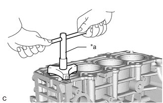
*a Alignment Mark - Using an E12 "TORX" socket wrench, remove the 2 connecting rod bolts and connecting rod cap.
HINT:
Keep the connecting rod bearing and connecting rod cap together.
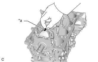
- Clean the crank pin and connecting rod bearing.
- Check the crank pin and connecting rod bearing for pitting and scratches.
HINT:
If the crank pin or connecting rod bearing is damaged, replace the connecting rod bearings. If necessary, replace the crankshaft.
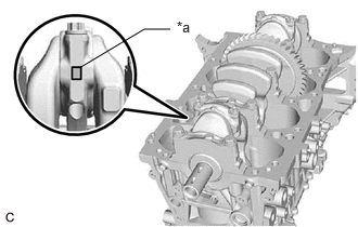
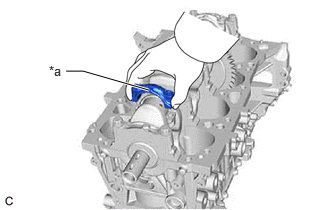
- Lay a strip of Plastigage on the crank pin.
*a Plastigage - except Cracking Connecting Rod:
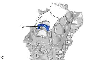
- Check that the front mark of the connecting rod cap is facing the correct direction, and install the connecting rod cap to the connecting rod.
*a Front Mark - Apply a light coat of engine oil to the threads and under the heads of the 2 connecting rod bolts.
- Using an E12 "TORX" socket wrench, install and uniformly tighten the 2 connecting rod bolts.
Torque: 10 N.m (102 kgf/cm, 7 ft.lbf)
- Using an E12 "TORX" socket wrench, alternately tighten the 2 connecting rod bolts.
Torque: 38 N.m (387 kgf/cm, 28 ft.lbf)
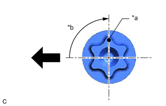
- Mark the front of each connecting rod bolt with paint.
*a Paint Mark *b 90° 
Front of Engine - Tighten the connecting rod bolts 90° as shown in the illustration.NOTE:
Do not turn the crankshaft during the measurement.
- Check that the paint marks are now at a 90° angle to the front.
- Check that the front mark of the connecting rod cap is facing the correct direction, and install the connecting rod cap to the connecting rod.
- Cracking Connecting Rod:
- Check that the front mark of the connecting rod cap is facing the correct direction, and install the connecting rod cap to the connecting rod.
*a Front Mark - Apply a light coat of engine oil to the threads and under the heads of the 2 connecting rod bolts.
- Using an E12 "TORX" socket wrench, install and uniformly tighten the 2 connecting rod bolts.
Torque: 10 N.m (102 kgf/cm, 7 ft.lbf)
NOTE:Do not use electric or air powered tools.
- Using an E12 "TORX" socket wrench, alternately tighten the 2 connecting rod bolts.
Torque: 38 N.m (387 kgf/cm, 28 ft.lbf)
- Mark the front of each connecting rod bolt with paint.
*a Paint Mark *b 90° Front of Engine - Tighten the connecting rod bolts 90° as shown in the illustration.NOTE:
Do not turn the crankshaft during the measurement.
- Check that the paint marks are now at a 90° angle to the front.
- Check that the front mark of the connecting rod cap is facing the correct direction, and install the connecting rod cap to the connecting rod.
- Remove the 2 connecting rod bolts and connecting rod cap.
HINT:
Keep the connecting rod bearing and connecting rod cap together.
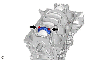
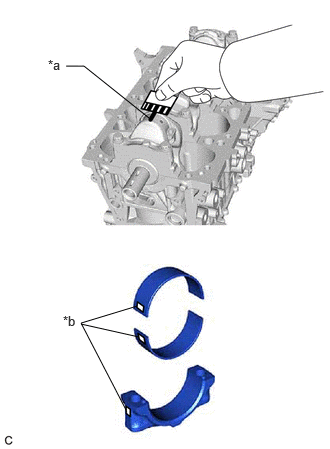
- Measure the Plastigage at its widest point.
*a Plastigage *b 1, 2 or 3 Mark Standard Oil Clearance
0.027 to 0.059 mm (0.00106 to 0.00232 in.)
Maximum Oil Clearance
0.059 mm (0.00232 in.)
HINT:
- If the oil clearance is more than the maximum, replace the connecting rod bearings. If necessary, replace the crankshaft.
- If replacing a connecting rod bearing, select a new one with the same number as marked on the connecting rod cap. There are 3 sizes of standard connecting rod bearings, marked "1", "2" or "3" accordingly.
Standard Connecting Rod Big End Inside Diameter
Mark Specified Condition 1 51.000 to 51.008 mm (2.00787 to 2.00818 in.) 2 51.009 to 51.016 mm (2.00822 to 2.00850 in.) 3 51.017 to 51.024 mm (2.00854 to 2.00881 in.) Standard Connecting Rod Bearing Center Wall Thickness
Mark Specified Condition 1 1.487 to 1.491 mm (0.0585 to 0.0587 in.) 2 1.492 to 1.495 mm (0.0587 to 0.0589 in.) 3 1.496 to 1.499 mm (0.0589 to 0.0590 in.) Standard Crank Pin Diameter
47.992 to 48.000 mm (1.88945 to 1.88976 in.)
NOTE:Remove the Plastigage completely after the measurement.
- Perform the inspection above for each cylinder.
- Note the alignment marks on the connecting rod and connecting rod cap so that they can be reinstalled to their original locations.
- REMOVE PISTON WITH CONNECTING ROD
- Using a ridge reamer, remove all the carbon from the top of each cylinder.
*a Ridge Reamer - Remove the 8 connecting rod bolts, 4 connecting rod caps and 4 connecting rod bearings.
- Push the 4 pistons, 4 connecting rods and 4 connecting rod bearings out through the top of the cylinder block sub-assembly.
HINT:
- Keep the connecting rod bearings, connecting rods and connecting rod caps together.
- Arrange the removed parts in such a way that they can be reinstalled to their original locations.
- Using a ridge reamer, remove all the carbon from the top of each cylinder.
- REMOVE CONNECTING ROD BEARING
- Remove the 8 connecting rod bearings from the 4 connecting rods and 4 connecting rod caps.
HINT:
Arrange the removed parts in such a way that they can be reinstalled to their original locations.
- Remove the 8 connecting rod bearings from the 4 connecting rods and 4 connecting rod caps.
- INSPECT CRANKSHAFT THRUST CLEARANCE
- Using a dial indicator, measure the crankshaft thrust clearance while prying the crankshaft back and forth with a screwdriver.
Standard Thrust Clearance
0.09 to 0.19 mm (0.00354 to 0.00748 in.)
Maximum Thrust Clearance
0.25 mm (0.00984 in.)
HINT:
If the thrust clearance is more than the maximum, replace the crankshaft thrust washers as a set. If necessary, replace the crankshaft.
Standard Thrust Washer Thickness
2.43 to 2.48 mm (0.0957 to 0.0976 in.)
- Using a dial indicator, measure the crankshaft thrust clearance while prying the crankshaft back and forth with a screwdriver.
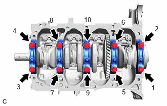
- REMOVE CRANKSHAFT
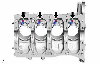
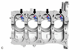
- Uniformly loosen and remove the 10 crankshaft bearing cap set bolts in several steps in the order shown in the illustration.
- Remove the 5 crankshaft bearing caps from the cylinder block sub-assembly.
HINT:
- Keep the No. 2 crankshaft bearings and crankshaft bearing caps together.
- Arrange the removed parts in such a way that they can be reinstalled to their original locations.
- Remove the crankshaft from the cylinder block sub-assembly.
HINT:
Keep the crankshaft bearings and crankshaft thrust washers together with the cylinder block sub-assembly.
- Check each crankshaft journal and crankshaft bearing for pitting and scratches.
If the journal or crankshaft bearing is damaged, replace the crankshaft bearings. If necessary, replace the crankshaft.
- Uniformly loosen and remove the 10 crankshaft bearing cap set bolts in several steps in the order shown in the illustration.
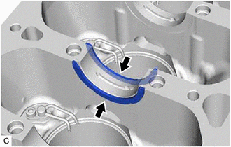
- REMOVE CRANKSHAFT THRUST WASHER
- REMOVE CRANKSHAFT BEARING
- Remove the 5 crankshaft bearings and 5 No. 2 crankshaft bearings from the cylinder block sub-assembly and 5 crankshaft bearing caps.
HINT:
Arrange the removed parts in such a way that they can be reinstalled to their original locations.
- Remove the 5 crankshaft bearings and 5 No. 2 crankshaft bearings from the cylinder block sub-assembly and 5 crankshaft bearing caps.
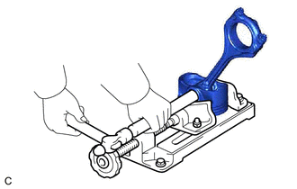
- REMOVE PISTON RING SET
- Using a piston ring expander, remove the No. 1 compression ring and No. 2 compression ring from the piston.
*a Piston Ring Expander - Remove the oil ring expander, upper side rail and lower side rail from the piston by hand.
HINT:
Arrange the removed parts in such a way that they can be reinstalled to their original locations.
- Using a piston ring expander, remove the No. 1 compression ring and No. 2 compression ring from the piston.
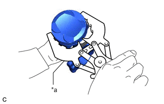
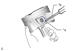
- REMOVE PISTON PIN HOLE SNAP RING
- REMOVE PISTON
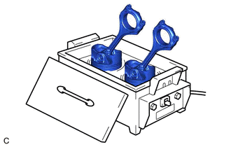
- Gradually heat each piston to between 80 and 90°C (176 and 194°F).WARNING:
Be sure to wear protective gloves.
- Using a brass bar and a hammer, lightly tap out the piston pin and remove the connecting rod.
HINT:
- The piston and piston pin are a matched set.
- Arrange the removed parts in such a way that they can be reinstalled to their original locations.
- Gradually heat each piston to between 80 and 90°C (176 and 194°F).
- REMOVE NO. 1 OIL NOZZLE SUB-ASSEMBLY
- REMOVE NO. 2 OIL NOZZLE SUB-ASSEMBLY