Inspection [12/2019 - ]: Procedure
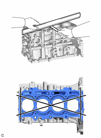
- INSPECT CYLINDER BLOCK FOR WARPAGE
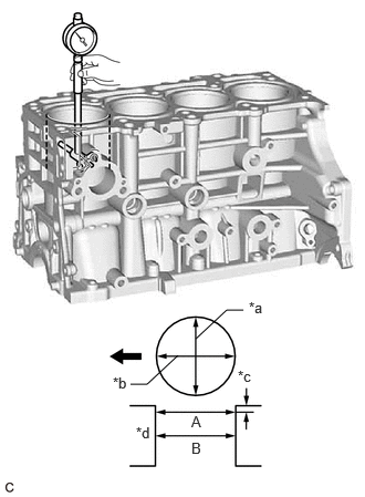
- INSPECT CYLINDER BORE
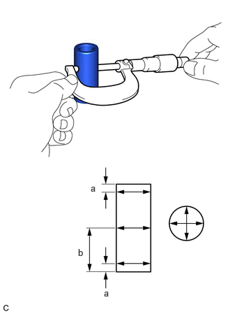
- Using a cylinder gauge, measure the cylinder bore diameter at the positions (A) and (B) in the thrust and axial directions.
*a Thrust Direction *b Axial Direction *c 10 mm (0.394 in.) *d Center 
Front of Engine Reference Diameter (New Parts)
87.500 to 87.513 mm (3.44488 to 3.44539 in.)
Maximum Diameter
87.63 mm (3.45 in.)
HINT:
If the average diameter of 4 positions is more than the maximum, replace the cylinder block sub-assembly.
- Using a cylinder gauge, measure the cylinder bore diameter at the positions (A) and (B) in the thrust and axial directions.
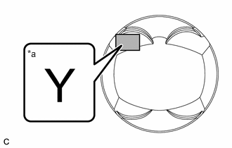
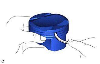
- INSPECT PISTON
HINT:
The identification mark is on the piston.
*a Identification Mark Y - INSPECT PISTON OIL CLEARANCE
- except Identification Mark Y:
- Subtract the piston diameter measurement from the cylinder bore diameter measurement.
Reference Oil Clearance (New Parts)
-0.002 to 0.041 mm (-0.0000787 to 0.00161 in.)
Maximum Oil Clearance
0.081 mm (0.00319 in.)
HINT:
If the piston oil clearance is more than the maximum, replace all the pistons with piston pins. If necessary, replace the cylinder block sub-assembly.
- Subtract the piston diameter measurement from the cylinder bore diameter measurement.
- for Identification Mark Y:
- Subtract the piston diameter measurement from the cylinder bore diameter measurement.
Reference Oil Clearance (New Parts)
0.005 to 0.048 mm (0.000197 to 0.00189 in.)
Maximum Oil Clearance
0.088 mm (0.00346 in.)
HINT:
If the piston oil clearance is more than the maximum, replace all the pistons with piston pins. If necessary, replace the cylinder block sub-assembly.
- Subtract the piston diameter measurement from the cylinder bore diameter measurement.
- except Identification Mark Y:
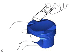
- INSPECT RING GROOVE CLEARANCE
- Using a feeler gauge, measure the clearance between a new piston ring set and the wall of the ring groove.
Standard Ring Groove Clearance
Item Specified Condition No. 1 compression ring 0.020 to 0.065 mm (0.000787 to 0.00256 in.) No. 2 compression ring 0.020 to 0.055 mm (0.000787 to 0.00217 in.) Oil ring 0.060 to 0.110 mm (0.00236 to 0.00433 in.) HINT:
If the groove clearance is not as specified, replace the piston and piston pin as a set.
- Using a feeler gauge, measure the clearance between a new piston ring set and the wall of the ring groove.
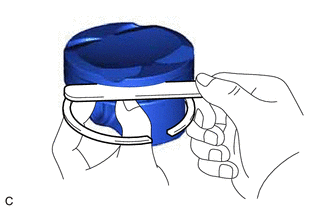
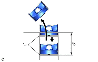
- INSPECT PISTON RING END GAP
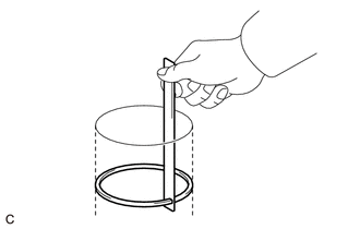
- Insert the piston ring into the cylinder bore.
*a Piston Ring *b 70 mm - Using a piston, push in the piston ring a little beyond the bottom of the ring travel, 70 mm (2.76 in.) from the top of the cylinder block sub-assembly.
- Using a feeler gauge, measure the end gap.
Standard End Gap
Item Specified Condition No. 1 compression ring 0.21 to 0.24 mm (0.00827 to 0.00945 in.) No. 2 compression ring 0.50 to 0.55 mm (0.0197 to 0.0217 in.) Oil ring 0.10 to 0.30 mm (0.00394 to 0.0118 in.) Maximum End Gap
Item Specified Condition No. 1 compression ring 0.49 mm (0.0193 in.) No. 2 compression ring 0.80 mm (0.0315 in.) Oil ring 0.55 mm (0.0217 in.) HINT:
If the end gap is more than the maximum, replace the piston ring set. If the end gap is more than the maximum even with a new piston ring set, replace the cylinder block sub-assembly.
- Insert the piston ring into the cylinder bore.
- INSPECT PISTON PIN OIL CLEARANCE
HINT:
When replacing the piston and piston pin with supply parts, there are a number of piston diameter sizes to choose from, but there is only one size of piston pin diameter.
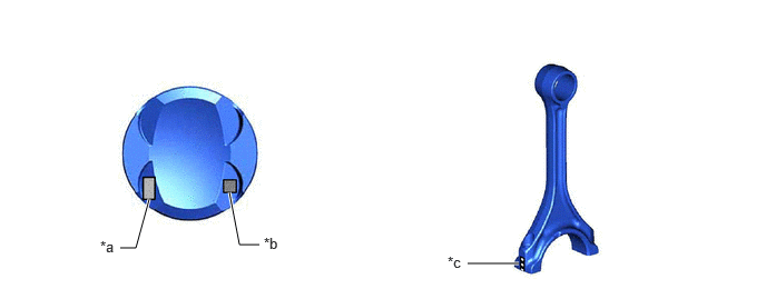
- Confirm each mark on the piston, piston pin and connecting rod.
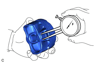
*a Front Mark *b Piston Pin Hole Inside Diameter Mark *c Connecting Rod Small End Bush Inside Diameter Mark - - - Using a caliper gauge, measure the inside diameter of the piston pin hole.
Standard Piston Pin Hole Inside Diameter
21.006 to 21.015 mm (0.82701 to 0.82736 in.)
Mark Specified Condition A 21.006 to 21.009 mm (0.82701 to 0.82712 in.) B 21.010 to 21.012 mm (0.82716 to 0.82724 in.) C 21.013 to 21.015 mm (0.82728 to 0.82736 in.) HINT:
If the diameter is not as specified, replace the piston and piston pin as a set.
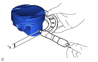
- Using a micrometer, measure the piston pin diameter.
Standard Piston Pin Diameter
21.004 to 21.013 mm (0.82693 to 0.82728 in.)
Mark Specified Condition A 21.004 to 21.007 mm (0.82693 to 0.82705 in.) B 21.008 to 21.010 mm (0.82708 to 0.82716 in.) C 21.011 to 21.013 mm (0.82720 to 0.82728 in.) HINT:
If the diameter is not as specified, replace the piston and piston pin as a set.
Measurement Position
Measurement Position Piston Pin Position a 5.0 mm (0.197 in.) from side edge b 24.5 mm (0.965 in.) from side edge - Using a caliper gauge, measure the inside diameter of the connecting rod small end bush.
Standard Connecting Rod Small End Bush Inside Diameter
21.012 to 21.021 mm (0.82724 to 0.82760 in.)
Mark Specified Condition A 21.012 to 21.015 mm (0.82724 to 0.82736 in.) B 21.016 to 21.018 mm (0.82740 to 0.82748 in.) C 21.019 to 21.021 mm (0.82752 to 0.82760 in.) HINT:
If the inside diameter is not as specified, replace the connecting rod sub-assembly.
- Subtract the piston pin diameter measurement from the piston pin hole inside diameter measurement.
Standard Oil Clearance
-0.001 to 0.005 mm (-0.0000394 to 0.000197 in.)
Maximum Oil Clearance
0.015 mm (0.000591 in.)
HINT:
If the oil clearance is more than the maximum, replace the piston and piston pin as a set.
- Subtract the piston pin diameter measurement from the connecting rod small end bush inside diameter measurement.
Standard Oil Clearance
0.005 to 0.011 mm (0.000197 to 0.000433 in.)
Maximum Oil Clearance
0.021 mm (0.000827 in.)
HINT:
If the oil clearance is more than the maximum, replace the connecting rod sub-assembly. If necessary, replace the connecting rod sub-assembly and piston pin as a set.
- Confirm each mark on the piston, piston pin and connecting rod.
- INSPECT CONNECTING ROD
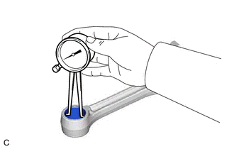
- Using a connecting rod aligner and feeler gauge, check the connecting rod alignment.
- Check for misalignment.
Maximum Misalignment
0.05 mm (0.00197 in.) per 100 mm (3.94 in.)
If the misalignment is more than the maximum, replace the connecting rod.
- Check for twist.
Maximum Twist
0.15 mm (0.00591 in.) per 100 mm (3.94 in.)
If the twist is more than the maximum, replace the connecting rod.
- Check for misalignment.
- Using a connecting rod aligner and feeler gauge, check the connecting rod alignment.
- INSPECT CRANKSHAFT
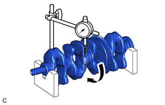
- Inspect for runout.
- Inspect the main journals.
- Using a micrometer, measure the diameter of each main journal.
Standard Main Journal Diameter
55.988 to 56.000 mm (2.20425 to 2.20472 in.)
HINT:
If the diameter is not as specified, check the crankshaft oil clearance. If necessary, replace the crankshaft.
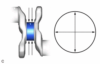
- Check each main journal for taper and out-of-round as shown in the illustration.
Maximum Taper and Out-of-round
0.003 mm (0.000118 in.)
HINT:
If the taper or out-of-round is more than the maximum, replace the crankshaft.
- Using a micrometer, measure the diameter of each main journal.
- Inspect the crank pins.
- Using a micrometer, measure the diameter of each crank pin.
Standard Crank Pin Diameter
47.992 to 48.000 mm (1.88945 to 1.88976 in.)
HINT:
If the diameter is not as specified, check the connecting rod oil clearance. If necessary, replace the crankshaft.
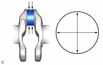
- Inspect each crank pin for taper and out-of-round as shown in the illustration.
Maximum Taper and Out-of-round
0.003 mm (0.000118 in.)
HINT:
If the taper or out-of-round is more than the maximum, replace the crankshaft.
- Using a micrometer, measure the diameter of each crank pin.
- INSPECT CRANKSHAFT OIL CLEARANCE
- Install the crankshaft bearings.
See step 5
- Install the crankshaft thrust washers.
See step 6
- Place the crankshaft on the cylinder block sub-assembly.
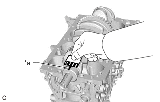
- Lay a strip of Plastigage across each journal.
*a Plastigage - Install the crankshaft bearing caps.
See step 7
NOTE:Do not turn the crankshaft.
- Remove the crankshaft bearing caps.
See step 7 [12/2019 - 10/2022], or see step 7 [10/2022 - 11/2023], or see step 7 [11/2023 - ]
- Measure the Plastigage at its widest point.
*a Plastigage Standard Oil Clearance
for No. 3 journal
0.020 to 0.043 mm (0.000787 to 0.00169 in.)
except No. 3 journal
0.014 to 0.037 mm (0.000551 to 0.00146 in.)
Maximum Oil Clearance
for No. 3 journal
0.044 mm (0.00173 in.)
except No. 3 journal
0.048 mm (0.00189 in.)
NOTE:Remove the Plastigage completely after the measurement.
If the oil clearance is more than the maximum, replace the crankshaft bearing. If necessary, replace the crankshaft.
HINT:
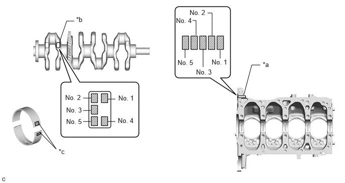
If replacing a crankshaft bearing, select a new one with the same number. If the number of the crankshaft bearing cannot be determined, calculate the correct crankshaft bearing number by adding together the numbers imprinted on the cylinder block sub-assembly and crankshaft. Then refer to the following table for the appropriate crankshaft bearing number. There are 4 sizes of standard bearings, marked "1", "2", "3", "4" or "5" accordingly.
*a Cylinder Block Number Mark (A) *b Crankshaft Number Mark (B) *c Diameter Mark - - - EXAMPLE
for No. 3 journal:
Cylinder block sub-assembly (A) "3" + Crankshaft (B) "4" = Total "7"
Select the crankshaft bearing marked "3".
except No. 3 journal:
Cylinder block sub-assembly (A) "3" + Crankshaft (B) "4" = Total "7"
Select the crankshaft bearing marked "4".
Crankshaft Bearing Chart (for No. 3 journal)
(A) + (B) Use Crankshaft Bearing 0 to 2 1 3 to 5 2 6 to 8 3 9 to 11 4 Crankshaft Bearing Chart (except No. 3 journal)
(A) + (B) Use Crankshaft Bearing 0 to 2 2 3 to 5 3 6 to 8 4 9 to 11 5 Standard Cylinder Block Journal Inside Diameter (A)
Mark Specified Condition 0 60.000 to 60.002 mm (2.36220 to 2.36228 in.) 1 60.003 to 60.004 mm (2.36232 to 2.36236 in.) 2 60.005 to 60.006 mm (2.36240 to 2.36244 in.) 3 60.007 to 60.009 mm (2.36248 to 2.36255 in.) 4 60.010 to 60.011 mm (2.36259 to 2.36263 in.) 5 60.012 to 60.013 mm (2.36267 to 2.36271 in.) 6 60.014 to 60.016 mm (2.36275 to 2.36283 in.) Standard Crankshaft Main Journal Diameter (B)
Mark Specified Condition 0 55.999 to 56.000 mm (2.20468 to 2.20472 in.) 1 55.997 to 55.998 mm (2.20460 to 2.20464 in.) 2 55.995 to 55.996 mm (2.20452 to 2.20456 in.) 3 55.993 to 55.994 mm (2.20444 to 2.20448 in.) 4 55.991 to 55.992 mm (2.20437 to 2.20441 in.) 5 55.988 to 55.990 mm (2.20425 to 2.20433 in.) Standard Crankshaft Bearing Center Wall Thickness
Mark Specified Condition 1 1.990 to 1.993 mm (0.07835 to 0.07846 in.) 2 1.994 to 1.996 mm (0.07850 to 0.07858 in.) 3 1.997 to 1.999 mm (0.07862 to 0.07870 in.) 4 2.000 to 2.002 mm (0.07874 to 0.07882 in.) 5 2.003 to 2.005 mm (0.07886 to 0.07894 in.)
- EXAMPLE
- Perform the inspection for each journal.
- Install the crankshaft bearings.
- INSPECT CRANKSHAFT BEARING CAP SET BOLT
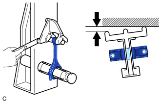
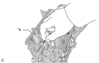
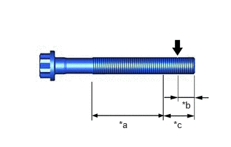
- Using a vernier caliper, measure the outer diameter at position A shown in the illustration.
*a Measurement Area B *b 5.0 mm (0.197 in.) *c 10 mm (0.394 in.) Measurement Location A Standard Diameter
10.73 to 10.97 mm (0.422 to 0.432 in.)
- Using a vernier caliper, measure the outer diameter within range B shown in the illustration at several locations.
HINT:
- Perform the measurement within range B at several locations.
- If the threads of the crankshaft bearing cap set bolt are damaged, replace the bolt with a new one.
- Calculate the difference between the measurement at position A and position B.
Minimum Diameter
The outer diameter difference is 0.3 mm (0.0118 in.)
HINT:
- Outer Diameter Difference = Position A Outer Diameter - Position B Outer Diameter (Smallest Value)
- If the outer diameter is below the minimum, the engine may be damaged.
Therefore, replace the crankshaft bearing cap set bolt with a new one.
- Using a vernier caliper, measure the outer diameter at position A shown in the illustration.
- INSPECT CONNECTING ROD BOLT
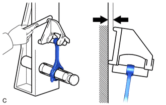
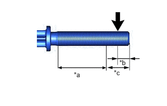
- Using a vernier caliper, measure the outer diameter at position A shown in the illustration.
*a Measurement Area B *b 5.0 mm (0.197 in.) *c 10 mm (0.394 in.) Measurement Location A Standard Diameter
8.36 to 8.5 mm (0.329 to 0.335 in.)
- Using a vernier caliper, measure the outer diameter within range B shown in the illustration at several locations.
HINT:
- Perform the measurement within range B at several locations.
- If the threads of the connecting rod bolt are damaged, replace the bolt with a new one.
- Calculate the difference between the measurement at position A and position B.
Minimum Diameter
The outer diameter difference is 0.05 mm (0.00197 in.)
HINT:
- Outer Diameter Difference = Position A Outer Diameter - Position B Outer Diameter (Smallest Value)
- If the outer diameter is below the minimum, the engine may be damaged.
Therefore, replace the connecting rod bolt with a new one.
- Using a vernier caliper, measure the outer diameter at position A shown in the illustration.
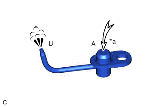
- INSPECT NO. 1 OIL NOZZLE SUB-ASSEMBLY
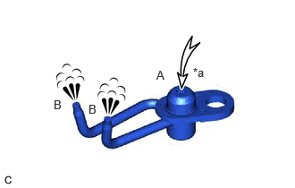
- INSPECT NO. 2 OIL NOZZLE SUB-ASSEMBLY