Removal [10/2022 - 11/2023]: Procedure
- REMOVE FRONT WHEEL
Refer to PROCEDURE - Step 1
- REMOVE FRONT WHEEL OPENING EXTENSION PAD LH
for A25A-FXS: Refer to PROCEDURE - Step 7
for T24A-FTS: Refer to PROCEDURE - Step 7
- REMOVE FRONT WHEEL OPENING EXTENSION PAD RH
for A25A-FXS: Refer to PROCEDURE - Step 8
for T24A-FTS: Refer to PROCEDURE - Step 8
- REMOVE NO. 1 ENGINE UNDER COVER
for A25A-FXS: Refer to PROCEDURE - Step 9
for T24A-FTS: Refer to PROCEDURE - Step 9
- REMOVE NO. 2 ENGINE UNDER COVER ASSEMBLY
for A25A-FXS: Refer to PROCEDURE - Step 10
for T24A-FTS: Refer to PROCEDURE - Step 10
- REMOVE FRONT FLOOR COVER LH (for LH Side)
for A25A-FXS: Refer to PROCEDURE - Step 34
for T24A-FTS: Refer to PROCEDURE - Step 3
- REMOVE FRONT FLOOR COVER RH (for RH Side)
for A25A-FXS: Refer to PROCEDURE - Step 35
for T24A-FTS: Refer to PROCEDURE - Step 14
- REMOVE FRONT FENDER APRON SEAL LH (for LH Side)
for A25A-FXS: Refer to PROCEDURE - Step 11
for T24A-FTS: Refer to PROCEDURE - Step 11
- REMOVE FRONT FENDER APRON SEAL RH (for RH Side)
for A25A-FXS: Refer to PROCEDURE - Step 12
for T24A-FTS: Refer to PROCEDURE - Step 12
- REMOVE FRONT LOWER NO. 1 SUSPENSION ARM SUB-ASSEMBLY
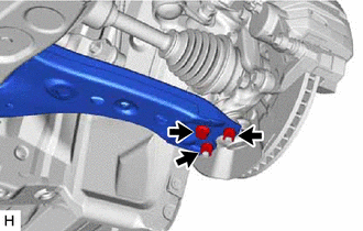
- Remove the bolt and 2 nuts and separate the front lower No. 1 suspension arm sub-assembly from the front lower ball joint assembly.
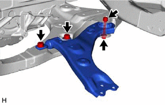
- Remove the 3 bolts, nut and front lower No. 1 suspension arm sub-assembly from the front frame assembly.NOTE:
Because the nut has its own stopper, do not turn the nut. Loosen the bolt with the nut secured.
- Remove the front lower arm bushing stopper from the front lower No. 1 suspension arm sub-assembly.
- Remove the bolt and 2 nuts and separate the front lower No. 1 suspension arm sub-assembly from the front lower ball joint assembly.