Installation [10/2022 - ]: Procedure
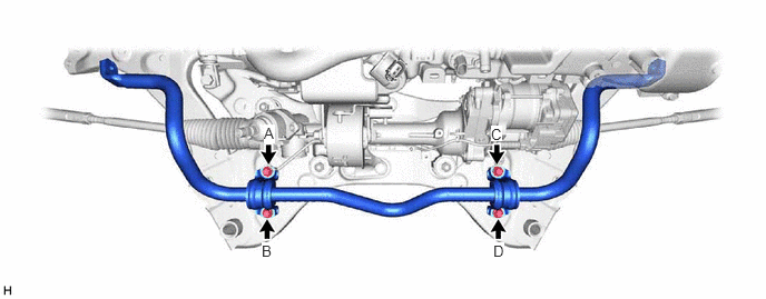
- INSTALL FRONT STABILIZER BAR SUB-ASSEMBLY
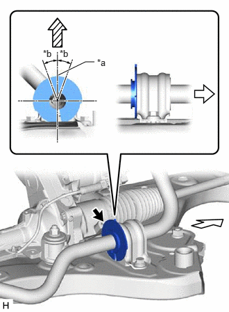
- INSTALL FRONT STABILIZER BAR PROTECTOR (for T24A-FTS)
- Install the stabilizer protector to the front stabilizer bar.NOTE:
- Install the stabilizer protector so that the protrusion is positioned as shown in the illustration.
- Make sure that the stabilizer protector is aligned within 20° from the center.
- Press the stabilizer protector so that it contacts the side of the front stabilizer bar bushing and install the stabilizer protector.
*a Protrusion *b 20° 
Right Side of Vehicle 
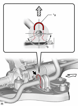
Upper Side of Vehicle - Install the clip.NOTE:
Make sure the curved top of the clip is not within the notch area.
*a Curved Top of Clip *b Notch Area Right Side of Vehicle Upper Side of Vehicle
- Install the stabilizer protector to the front stabilizer bar.
- INSTALL FRONT STABILIZER LINK ASSEMBLY LH
- Install the front stabilizer link assembly LH to the front stabilizer bar sub-assembly with the nut.
Torque: 74 N.m (755 kgf/cm, 55 ft.lbf)
NOTE:Do not damage the boot of the ball joint.
HINT:
If the ball joint turns together with the nut, use a 6 mm hexagon socket wrench to hold the stud bolt.
- Install the front stabilizer link assembly LH to the front stabilizer bar sub-assembly with the nut.
- INSTALL FRONT STABILIZER LINK ASSEMBLY RH
HINT:
Perform the same procedure as for the LH side.
- INSTALL ENGINE ASSEMBLY WITH TRANSAXLE
for A25A-FXS: Refer to PROCEDURE - Step 22 [10/2022 - 11/2023] , or refer to PROCEDURE - Step 21 [11/2023 - ]
for T24A-FTS: Refer to PROCEDURE - Step 31 [10/2022 - 11/2023] , or refer to PROCEDURE - Step 31 [11/2023 - ]