DTC B149A: Communication Malfunction (Rear Bus Ic) [12/2019 - 11/2023]: Procedure
- PERFORM ACTIVE TEST USING GTS (SERVO PULSE)
- Perform the Active Test according to the display on the GTS.
Body Electrical > Air Conditioner > Active Test
Tester Display Measurement Item Control Range Diagnostic Note Rear Air Mix Servo Targ Pulse Rear air mix damper servo sub-assembly pulse Min.: 128
Max.: 383Operates between 213 to 258 pulses A/O Servo Pulse (Rr D) Rear mode damper servo sub-assembly pulse Min.: 128
Max.: 383Operates between 200 to 276 pulses Body Electrical > Air Conditioner > Active Test
Tester Display Rear Air Mix Servo Targ Pulse Body Electrical > Air Conditioner > Active Test
Tester Display A/O Servo Pulse (Rr D) OK
Damper servo motor is operated.
Result
Result Proceed to All damper servo motors are not operated A Any damper servo motor is not operated B All damper servo motors are operated C
Result:
B
REPLACE NO. 2 AIR CONDITIONING HARNESS ASSEMBLY. Refer to DISASSEMBLY [12/2019 - ]
Result:
C
REPLACE AIR CONDITIONING AMPLIFIER ASSEMBLY. Refer to REMOVAL [12/2019 - 10/2022] , or refer to REMOVAL [10/2022 - 11/2023]
Result:
A
See step 2
- Perform the Active Test according to the display on the GTS.
- CHECK AIR CONDITIONING AMPLIFIER ASSEMBLY
- Disconnect the H64 air conditioning amplifier assembly connector.
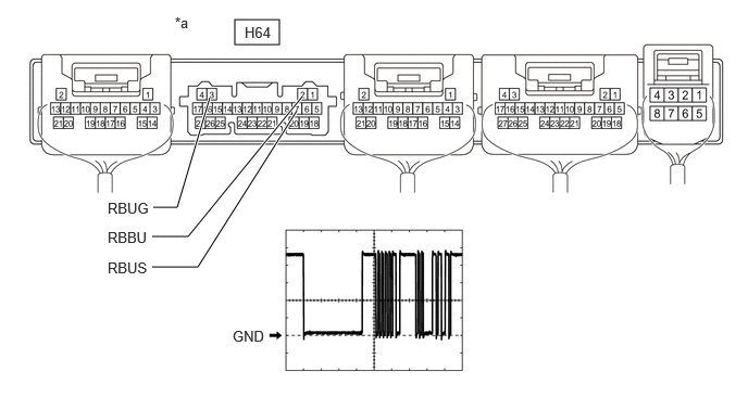
*a Component without harness connected
(Air Conditioning Amplifier Assembly)- - - Measure the resistance according to the value(s) in the table below.
Standard Resistance
Tester Connection Condition Specified Condition H64-3 (RBUG) - Body ground Always Below 1 Ω - Measure the voltage according to the value(s) in the table below.
Standard Voltage
Tester Connection Condition Specified Condition H64-2 (RBBU) - H64-3 (RBUG) Ignition switch off 11 to 14 V - Using an oscilloscope, check the waveform.
Item Content Tester Connection H64-7 (RBUS) - H64-3 (RBUG) Tool Setting 2 V/DIV., 20 μs/DIV. Condition Ignition switch ON OK
The waveform displays properly.
Result
Proceed to OK NG
Result:
NG
REPLACE AIR CONDITIONING AMPLIFIER ASSEMBLY. Refer to REMOVAL [12/2019 - 10/2022] , or refer to REMOVAL [10/2022 - 11/2023]
Result:
OK
See step 3
- Disconnect the H64 air conditioning amplifier assembly connector.
- CHECK HARNESS AND CONNECTOR (AIR CONDITIONING AMPLIFIER ASSEMBLY - NO. 2 AIR CONDITIONING HARNESS ASSEMBLY)
- Connect the H64 air conditioning amplifier assembly connector.
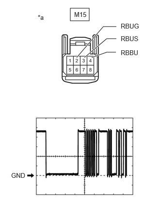
*a Front view of wire harness connector
(to No. 2 Air Conditioning Harness Assembly) - Disconnect the M15 No. 2 air conditioning harness assembly connector.
- Measure the resistance according to the value(s) in the table below.
Standard Resistance
Tester Connection Condition Specified Condition M15-2 (RBUG) - Body ground Always Below 1 Ω - Measure the voltage according to the value(s) in the table below.
Standard Voltage
Tester Connection Condition Specified Condition M15-4 (RBBU) - M15-2 (RBUG) Ignition switch off 11 to 14 V - Using an oscilloscope, check the waveform.
Item Content Tester Connection M15-3 (RBUS) - M15-2 (RBUG) Tool Setting 2 V/DIV., 20 μs/DIV. Condition Ignition switch ON OK
The waveform displays properly.
Result
Proceed to OK NG
Result:
OK
REPLACE NO. 2 AIR CONDITIONING HARNESS ASSEMBLY. Refer to DISASSEMBLY [12/2019 - ]
Result:
NG
REPAIR OR REPLACE HARNESS OR CONNECTOR (AIR CONDITIONING AMPLIFIER ASSEMBLY - NO. 2 AIR CONDITIONING HARNESS ASSEMBLY)
- Connect the H64 air conditioning amplifier assembly connector.