DTC B14B3-87: Lost Communication with Rear Panel LIN Missing Message [11/2023 - ]: Procedure
- CHECK HARNESS AND CONNECTOR (NO. 2 AIR CONDITIONING CONTROL ASSEMBLY - AUXILIARY BATTERY)
Pre-procedure1
- Disconnect the T2 No. 2 air conditioning control assembly connector.
Procedure1
- Measure the voltage according to the value(s) in the table below.
Standard Voltage
Tester Connection Condition Specified Condition T2-9 (IG) - Body ground Ignition switch ON 11 to 14 V Result
Proceed to OK NG Post-procedure1
- None
Result:
NG
REPAIR OR REPLACE HARNESS OR CONNECTOR
Result:
OK
See step 2
- Disconnect the T2 No. 2 air conditioning control assembly connector.
- CHECK HARNESS AND CONNECTOR (NO. 2 AIR CONDITIONING CONTROL ASSEMBLY - BODY GROUND)
Pre-procedure1
- Disconnect the T2 No. 2 air conditioning control assembly connector.
Procedure1
- Measure the resistance according to the value(s) in the table below.
Standard Resistance
Tester Connection Condition Specified Condition T2-7 (E) - Body ground Always Below 1 Ω Result
Proceed to OK NG Post-procedure1
- None
Result:
NG
REPAIR OR REPLACE HARNESS OR CONNECTOR
Result:
OK
See step 3
- Disconnect the T2 No. 2 air conditioning control assembly connector.
- CHECK HARNESS AND CONNECTOR (AIR CONDITIONING AMPLIFIER ASSEMBLY - NO. 2 AIR CONDITIONING CONTROL ASSEMBLY)
Pre-procedure1
- Disconnect the T2 No. 2 air conditioning control assembly connector.
- Disconnect the H64 air conditioning amplifier assembly connector.
Procedure1
- Measure the resistance according to the value(s) in the table below.
Standard Resistance
Tester Connection Condition Specified Condition T2-8 (RLIN) - H64-20 (RLIN) Always Below 1 Ω T2-8 (RLIN) or H64-20 (RLIN) - Other terminals and body ground Always 10 kΩ or higher Result
Proceed to OK NG Post-procedure1
- None
Result:
NG
REPAIR OR REPLACE HARNESS OR CONNECTOR
Result:
OK
See step 4
- CHECK AIR CONDITIONING AMPLIFIER ASSEMBLY (OUTPUT)
Pre-procedure1
- Disconnect the T2 No. 2 air conditioning control assembly connector.
- Connect the H64 air conditioning amplifier assembly connector.
Procedure1
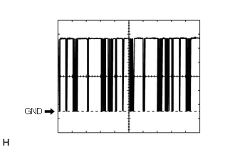
- Using an oscilloscope, check the waveform.
Item Content Tester Connection H64-20 (RLIN) - Body ground Tool Setting 2 V/DIV., 20 μs/DIV. Condition Ignition switch ON OK
The waveform displays properly.
Result
Proceed to OK NG Post-procedure1
- None
Result:
NG
REPLACE AIR CONDITIONING AMPLIFIER ASSEMBLY
Refer to REMOVAL [11/2023 - ]
Result:
OK
See step 5
- CHECK NO. 2 AIR CONDITIONING CONTROL ASSEMBLY (OUTPUT)
Pre-procedure1
- Connect the T2 No. 2 air conditioning control assembly connector.
Procedure1
- Using an oscilloscope, check the waveform.
Item Content Tester Connection T2-8 (RLIN) - Body ground Tool Setting 2 V/DIV., 20 μs/DIV. Condition Ignition switch ON OK
The waveform displays properly.
Result
Proceed to OK NG Post-procedure1
- None
Result:
OK
REPLACE AIR CONDITIONING AMPLIFIER ASSEMBLY
Refer to REMOVAL [11/2023 - ]
Result:
NG
REPLACE NO. 2 AIR CONDITIONING CONTROL ASSEMBLY
Refer to REMOVAL [12/2019 - ]
- Connect the T2 No. 2 air conditioning control assembly connector.