DTC P0530-15: Refrigerant Pressure Sensor Circuit Short to Battery or Open [11/2023 - ]: Procedure
- CHECK COMPARE REFRIGERANT GAS PRESSURE VALUES SHOWN ON GTS AND MANIFOLD GAUGE SET
Pre-procedure1
- Install a manifold gauge set.
HINT:
Refer to ON-VEHICLE INSPECTION [12/2019 - ]
Procedure1
- Compare the values displayed in the Data List and on the manifold gauge.
Body Electrical > Air Conditioner > Data List
Tester Display Measurement Item Range Normal Condition Diagnostic Note Regulator Pressure Sensor Air conditioning pressure sensor -32768 to 32767 kPa (gauge) (-32.768 to 32.767 MPaG) Actual refrigerant pressure displayed - Refrigerant line (gas leak etc.)
- Air conditioning pressure sensor circuit malfunction
Body Electrical > Air Conditioner > Data List
Tester Display Regulator Pressure Sensor Result
Result Proceed to Data List value and manifold gauge set value do not match A Data List value matches manifold gauge set value B Post-procedure1
- None
Result:
B
INSPECT REFRIGERANT PRESSURE WITH MANIFOLD GAUGE SET. Refer to ON-VEHICLE INSPECTION [12/2019 - ]
Result:
A
See step 2
- Install a manifold gauge set.
- CHECK HARNESS AND CONNECTOR (AIR CONDITIONING PRESSURE SENSOR - BODY GROUND)
Pre-procedure1
- Disconnect the A24 air conditioning pressure sensor connector.
Procedure1
- Measure the resistance according to the value(s) in the table below.
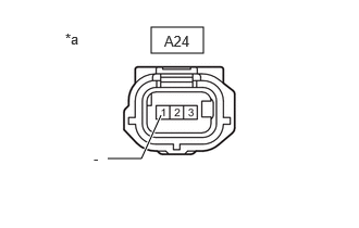
*a Front view of wire harness connector
(to Air Conditioning Pressure Sensor)Standard Resistance
Tester Connection Condition Specified Condition A24-1 (-) - Body ground Always Below 1 Ω Result
Proceed to OK NG Post-procedure1
- None
Result:
NG
See step 8
Result:
OK
See step 3
- Disconnect the A24 air conditioning pressure sensor connector.
- CHECK HARNESS AND CONNECTOR (AIR CONDITIONING PRESSURE SENSOR - BODY GROUND)
Pre-procedure1
- Disconnect the A24 air conditioning pressure sensor connector.
Procedure1
- Measure the voltage according to the value(s) in the table below.
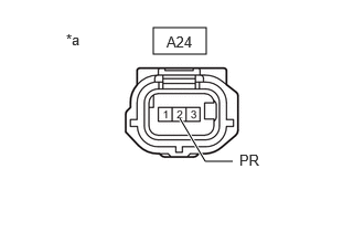
*a Front view of wire harness connector
(to Air Conditioning Pressure Sensor)Standard Voltage
Tester Connection Condition Specified Condition A24-2 (PR) - Body ground Ignition switch ON 3.0 to 5.25 V Result
Result Proceed to A24-2 (PR) - Body ground is more than 5.25 V A A24-2 (PR) - Body ground is more than or equal to 3.0 and less than or equal to 5.25 V B A24-2 (PR) - Body ground is less than 3.0 V C Post-procedure1
- None
Result:
B
See step 5
Result:
C
See step 7
Result:
A
See step 4
- Disconnect the A24 air conditioning pressure sensor connector.
- CHECK HARNESS AND CONNECTOR (AIR CONDITIONING AMPLIFIER ASSEMBLY - AIR CONDITIONING PRESSURE SENSOR)
Pre-procedure1
- Disconnect the A24 air conditioning pressure sensor connector.
- Disconnect the H63 air conditioning amplifier assembly connector.
Procedure1
- Measure the resistance according to the value(s) in the table below.
Standard Resistance
Tester Connection Condition Specified Condition A24-2 (PR) or H63-6 (PRE) - Other terminals and body ground Always 10 kΩ or higher Result
Proceed to OK NG Post-procedure1
- None
Result:
OK
REPLACE AIR CONDITIONING AMPLIFIER ASSEMBLY. Refer to REMOVAL [11/2023 - ]
Result:
NG
REPAIR OR REPLACE HARNESS OR CONNECTOR
- CHECK AIR CONDITIONING AMPLIFIER ASSEMBLY (INTERNAL CIRCUIT RESISTANCE)
Pre-procedure1
- Disconnect the A24 air conditioning pressure sensor connector.
Procedure1
- Measure the resistance according to the value(s) in the table below.
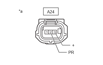
*a Front view of wire harness connector
(to Air Conditioning Pressure Sensor)Standard Resistance
Tester Connection Condition Specified Condition A24-3 (+) - A24-2 (PR) Ignition switch off 180 to 220 kΩ HINT:
After turning the ignition switch off, wait at least 30 seconds before performing the measurement.
Result
Proceed to OK NG Post-procedure1
- None
Result:
OK
REPLACE AIR CONDITIONING PRESSURE SENSOR. Refer to REMOVAL [10/2022 - ]
Result:
NG
See step 6
- Disconnect the A24 air conditioning pressure sensor connector.
- CHECK HARNESS AND CONNECTOR (AIR CONDITIONING PRESSURE SENSOR - AIR CONDITIONING AMPLIFIER ASSEMBLY)
Pre-procedure1
- Disconnect the A24 air conditioning pressure sensor connector.
- Disconnect the H63 air conditioning amplifier assembly connector.
Procedure1
- Measure the resistance according to the value(s) in the table below.
Standard Resistance
Tester Connection Condition Specified Condition A24-2 (PR) - A24-3 (+) Always 10 kΩ or higher H63-6 (PRE) - H63-11 (S5-3) Always 10 kΩ or higher Result
Proceed to OK NG Post-procedure1
- None
Result:
OK
REPLACE AIR CONDITIONING AMPLIFIER ASSEMBLY. Refer to REMOVAL [11/2023 - ]
Result:
NG
REPAIR OR REPLACE HARNESS OR CONNECTOR
- CHECK HARNESS AND CONNECTOR (AIR CONDITIONING AMPLIFIER ASSEMBLY - AIR CONDITIONING PRESSURE SENSOR)
Pre-procedure1
- Disconnect the A24 air conditioning pressure sensor connector.
- Disconnect the H63 air conditioning amplifier assembly connector.
Procedure1
- Measure the resistance according to the value(s) in the table below.
Standard Resistance
Tester Connection Condition Specified Condition A24-2 (PR) - H63-6 (PRE) Always Below 1 Ω Result
Proceed to OK NG Post-procedure1
- None
Result:
OK
REPLACE AIR CONDITIONING AMPLIFIER ASSEMBLY. Refer to REMOVAL [11/2023 - ]
Result:
NG
REPAIR OR REPLACE HARNESS OR CONNECTOR
- CHECK HARNESS AND CONNECTOR (AIR CONDITIONING AMPLIFIER ASSEMBLY - AIR CONDITIONING PRESSURE SENSOR)
Pre-procedure1
- Disconnect the A24 air conditioning pressure sensor connector.
- Disconnect the H63 air conditioning amplifier assembly connector.
Procedure1
- Measure the resistance according to the value(s) in the table below.
Standard Resistance
Tester Connection Condition Specified Condition A24-1 (-) - H63-15 (SG-4) Always Below 1 Ω Result
Proceed to OK NG Post-procedure1
- None
Result:
OK
REPLACE AIR CONDITIONING AMPLIFIER ASSEMBLY. Refer to REMOVAL [11/2023 - ]
Result:
NG
REPAIR OR REPLACE HARNESS OR CONNECTOR