DTC P0535-15: Evaporator Temperature Sensor Circuit Short to Battery or Open [11/2023 - ]: Procedure
- CHECK EVAPORATOR TEMP. SENSOR (NO. 1 COOLER THERMISTOR) CIRCUIT
Pre-procedure1
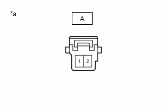
- Disconnect the A evaporator temp. sensor (No. 1 cooler thermistor) connector.
*a Front view of wire harness connector
(to Evaporator Temp. Sensor (No. 1 Cooler Thermistor))Procedure1
- Measure the voltage according to the value(s) in the table below.
Standard Voltage
Tester Connection Condition Specified Condition A-2 - Body ground Ignition switch ON 0 to 5.5 V Result
Proceed to OK NG Post-procedure1
- None
Result:
NG
See step 5
Result:
OK
See step 2
- Disconnect the A evaporator temp. sensor (No. 1 cooler thermistor) connector.
- CLEAR DTC
Result:
NEXT
See step 3
- CHECK FOR DTC
Pre-procedure1
- Turn the ignition switch off.
- Disconnect the A evaporator temp. sensor (No. 1 cooler thermistor) connector.
*a Front view of wire harness connector
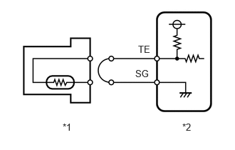
(to Evaporator Temp. Sensor (No. 1 Cooler Thermistor)) - Connect terminals 1 and 2 of the evaporator temp. sensor (No. 1 cooler thermistor) connector on the wire harness side.
*1 Evaporator Temp. Sensor (No. 1 Cooler Thermistor) *2 Air Conditioning Amplifier Assembly - Turn the ignition switch to ON and wait for 4 seconds or more.
Procedure1
- Check for DTCs.
Body Electrical > Air Conditioner > Trouble Codes
Result
Result Proceed to P0535-11 is output A P0535-15 is output B Post-procedure1
- None
Result:
A
REPLACE EVAPORATOR TEMP. SENSOR (NO. 1 COOLER THERMISTOR)
Refer to REMOVAL [11/2023 - ]
Result:
B
See step 4
- INSPECT AIR CONDITIONING HARNESS ASSEMBLY (EVAPORATOR TEMP. SENSOR (NO. 1 COOLER THERMISTOR) - AIR CONDITIONING AMPLIFIER ASSEMBLY)
Pre-procedure1
- Remove the air conditioning harness assembly.
HINT:
Refer to DISASSEMBLY [10/2022 - ]
Procedure1
- Measure the resistance according to the value(s) in the table below.
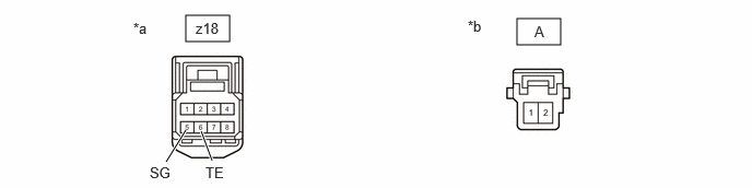
*a Front view of air conditioning harness assembly connector
(to Air Conditioning Amplifier Assembly)*b Front view of air conditioning harness assembly connector
(to Evaporator Temp. Sensor (No. 1 Cooler Thermistor))Standard Resistance
Tester Connection Condition Specified Condition A-2 - z18-6 (TE) Always Below 1 Ω A-1 - z18-5 (SG) Always Below 1 Ω Result
Proceed to OK NG Post-procedure1
- None
Result:
OK
REPLACE AIR CONDITIONING AMPLIFIER ASSEMBLY
Refer to REMOVAL [11/2023 - ]
Result:
NG
REPLACE AIR CONDITIONING HARNESS ASSEMBLY
Refer to DISASSEMBLY [10/2022 - ]
- Remove the air conditioning harness assembly.
- INSPECT AIR CONDITIONING HARNESS ASSEMBLY (EVAPORATOR TEMP. SENSOR (NO. 1 COOLER THERMISTOR) - AIR CONDITIONING AMPLIFIER ASSEMBLY)
Pre-procedure1
- Remove the air conditioning harness assembly.
HINT:
Refer to DISASSEMBLY [10/2022 - ]
Procedure1
- Measure the resistance according to the value(s) in the table below.
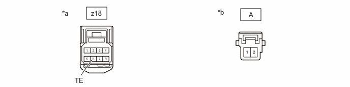
*a Front view of air conditioning harness assembly connector
(to Air Conditioning Amplifier Assembly)*b Front view of air conditioning harness assembly connector
(to Evaporator Temp. Sensor (No. 1 Cooler Thermistor))Standard Resistance
Tester Connection Condition Specified Condition A-2 or z18-6 (TE) - Other terminals and body ground Always 10 kΩ or higher Result
Proceed to OK NG Post-procedure1
- None
Result:
OK
REPLACE AIR CONDITIONING AMPLIFIER ASSEMBLY
Refer to REMOVAL [11/2023 - ]
Result:
NG
REPLACE AIR CONDITIONING HARNESS ASSEMBLY
Refer to DISASSEMBLY [10/2022 - ]
- Remove the air conditioning harness assembly.