DTC P058A-01: Auxiliary Battery Monitor Module Range/Performance [12/2019 - 11/2023]: Procedure
WARNING: This page is about a different variant/trim than selected.
- CHECK BATTERY STATE SENSOR ASSEMBLY
Result:
NG
INSTALL THE BATTERY STATE SENSOR ASSEMBLY CORRECTLY. Refer to INSTALLATION [12/2019 - 11/2023]
Result:
OK
See step 2
- CHECK HARNESS AND CONNECTOR (POWER SOURCE CIRCUIT)
- Check that the battery state sensor assembly connector is securely connected.
OK
The connector is securely connected.
- Disconnect the M7 battery state sensor assembly connector.
- Check the connector case and terminals for deformation or corrosion.
OK
No deformation or corrosion.
- Measure the voltage according to the value(s) in the table below.
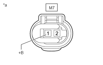
*a Front view of wire harness connector
(to Battery State Sensor Assembly)Standard Voltage
Tester Connection Condition Specified Condition M7-1 (+B) - Body ground Ignition switch off 11 to 14 V Result
Proceed to OK NG
Result:
OK
REPLACE BATTERY STATE SENSOR ASSEMBLY. Refer to REMOVAL [12/2019 - 10/2022] , or refer to REMOVAL [10/2022 - 11/2023]
Result:
NG
REPAIR OR REPLACE HARNESS OR CONNECTOR (AUXILIARY BATTERY - BATTERY STATE SENSOR ASSEMBLY)
- Check that the battery state sensor assembly connector is securely connected.