DTC U111A-87: Lost Communication with ECM/PCM "A" (ch2) Missing Message; DTC U1150-00: Lost Communication with Hybrid Powertrain Control Module (ch2); DTC U1150-87: Lost Communication with Hybrid Powertrain Control Module (ch2) Missing Message; DTC U1159-87: Lost Communication with Electronic Brake Booster Control Module "A" (ch3) Missing Message; DTC U1170-87: Lost Communication with Brake System Control Module (Secondary CAN Line) Missing Message; DTC U117D-87: Lost Communication with Brake System Control Module (ch4) Missing Message [11/2023 - ]: Procedure
- CHECK FOR OPEN IN CAN MAIN BUS LINES
- Disconnect the cable from the negative (-) auxiliary battery terminal.
- Measure the resistance according to the value(s) in the table below.
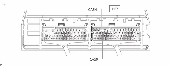
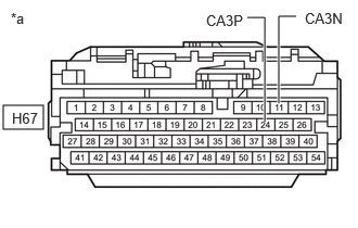
*a Component with harness connected
(Hybrid Vehicle Control ECU)- - Standard Resistance
Tester Connection Condition Specified Condition H67-24 (CA3P) - H67-11 (CA3N) Cable disconnected from negative (-) auxiliary battery terminal Below 70 Ω Result
Proceed to OK NG
Result:
NG
See step 29
Result:
OK
See step 2
- CHECK FOR SHORT IN CAN BUS LINES
- Measure the resistance according to the value(s) in the table below.
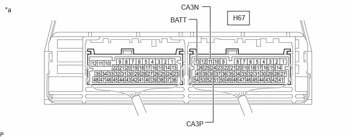
*a Component with harness connected
(Hybrid Vehicle Control ECU)- - Standard Resistance
Tester Connection Condition Specified Condition H67-24 (CA3P) - H67-11 (CA3N) Cable disconnected from negative (-) auxiliary battery terminal 54 Ω or higher Result
Proceed to OK NG
Result:
NG
See step 21
Result:
OK
See step 3
- Measure the resistance according to the value(s) in the table below.
- CHECK FOR SHORT TO +B IN CAN BUS LINE
- Measure the resistance according to the value(s) in the table below.
*a Component with harness connected
(Hybrid Vehicle Control ECU)- - Standard Resistance
Tester Connection Condition Specified Condition H67-24 (CA3P) - H67-13 (BATT) Cable disconnected from negative (-) auxiliary battery terminal 6 kΩ or higher H67-11 (CA3N) - H67-13 (BATT) Result
Proceed to OK NG
Result:
NG
See step 13
Result:
OK
See step 4
- Measure the resistance according to the value(s) in the table below.
- CHECK FOR SHORT TO GND IN CAN BUS LINE
- Measure the resistance according to the value(s) in the table below.
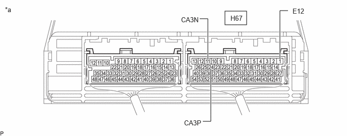
*a Component with harness connected
(Hybrid Vehicle Control ECU)- - Standard Resistance
Tester Connection Condition Specified Condition H67-24 (CA3P) - H67-1 (E12) Cable disconnected from negative (-) auxiliary battery terminal 200 Ω or higher H67-11 (CA3N) - H67-1 (E12) Result
Proceed to OK NG
Result:
OK
INSPECT FOR INTERMITTENT PROBLEMS
Refer to HOW TO PROCEED WITH TROUBLESHOOTING [12/2019 - ]
Result:
NG
See step 5
- Measure the resistance according to the value(s) in the table below.
- CHECK FOR SHORT TO GND IN CAN BUS LINE (NO. 1 GLOBAL CAN JUNCTION CONNECTOR - HYBRID VEHICLE CONTROL ECU)
- Disconnect the A93 No. 1 global CAN junction connector.
- Measure the resistance according to the value(s) in the table below.
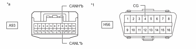
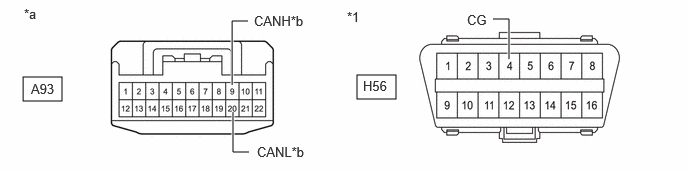
*1 DLC3 - - *a Front view of wire harness connector
(to No. 1 Global CAN Junction Connector)*b to Hybrid Vehicle Control ECU Standard Resistance
Tester Connection Condition Specified Condition A93-8 (CANH) - H56-4 (CG) Cable disconnected from negative (-) auxiliary battery terminal 200 Ω or higher A93-19 (CANL) - H56-4 (CG) Result
Proceed to OK NG
Result:
NG
See step 9
Result:
OK
See step 6
- CHECK FOR SHORT TO GND IN CAN BUS LINE (NO. 1 GLOBAL CAN JUNCTION CONNECTOR - ECM)
- Measure the resistance according to the value(s) in the table below.
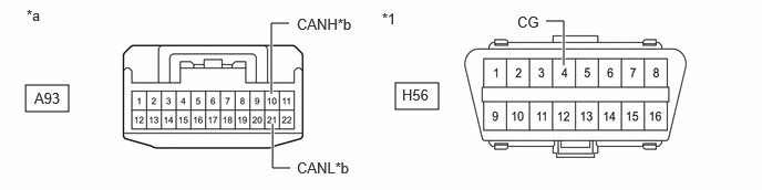
*1 DLC3 - - *a Front view of wire harness connector
(to No. 1 Global CAN Junction Connector)*b to ECM Standard Resistance
Tester Connection Condition Specified Condition A93-9 (CANH) - H56-4 (CG) Cable disconnected from negative (-) auxiliary battery terminal 200 Ω or higher A93-20 (CANL) - H56-4 (CG) Result
Proceed to OK NG
Result:
NG
See step 10
Result:
OK
See step 7
- Measure the resistance according to the value(s) in the table below.
- CHECK FOR SHORT TO GND IN CAN BUS LINE (NO. 1 GLOBAL CAN JUNCTION CONNECTOR - NO. 1 SKID CONTROL ECU (BRAKE BOOSTER WITH MASTER CYLINDER ASSEMBLY))
- Measure the resistance according to the value(s) in the table below.
*1 DLC3 - - *a Front view of wire harness connector
(to No. 1 Global CAN Junction Connector)*b to No. 1 Skid Control ECU (Brake Booster with Master Cylinder Assembly) Standard Resistance
Tester Connection Condition Specified Condition A93-10 (CANH) - H56-4 (CG) Cable disconnected from negative (-) auxiliary battery terminal 200 Ω or higher A93-21 (CANL) - H56-4 (CG) Result
Proceed to OK NG
Result:
NG
See step 11
Result:
OK
See step 8
- Measure the resistance according to the value(s) in the table below.
- CHECK FOR SHORT TO GND IN CAN BUS LINE (NO. 1 GLOBAL CAN JUNCTION CONNECTOR - NO. 2 SKID CONTROL ECU (BRAKE ACTUATOR ASSEMBLY))
- Measure the resistance according to the value(s) in the table below.
*1 DLC3 - - *a Front view of wire harness connector
(to No. 1 Global CAN Junction Connector)*b to No. 2 Skid Control ECU (Brake Actuator Assembly) Standard Resistance
Tester Connection Condition Specified Condition A93-11 (CANH) - H56-4 (CG) Cable disconnected from negative (-) auxiliary battery terminal 200 Ω or higher A93-22 (CANL) - H56-4 (CG) Result
Proceed to OK NG
Result:
OK
REPLACE NO. 1 GLOBAL CAN JUNCTION CONNECTOR
Result:
NG
See step 12
- Measure the resistance according to the value(s) in the table below.
- CHECK FOR SHORT TO GND IN CAN BUS LINE (NO. 1 GLOBAL CAN JUNCTION CONNECTOR - HYBRID VEHICLE CONTROL ECU)
- Disconnect the H67 hybrid vehicle control ECU connector.
- Measure the resistance according to the value(s) in the table below.
*1 DLC3 - - *a Front view of wire harness connector
(to No. 1 Global CAN Junction Connector)*b to Hybrid Vehicle Control ECU Standard Resistance
Tester Connection Condition Specified Condition A93-8 (CANH) - H56-4 (CG) Cable disconnected from negative (-) auxiliary battery terminal 200 Ω or higher A93-19 (CANL) - H56-4 (CG) Result
Proceed to OK NG
Result:
OK
REPLACE HYBRID VEHICLE CONTROL ECU
Refer to REMOVAL [11/2023 - ]
Result:
NG
REPAIR OR REPLACE CAN MAIN BUS LINE OR CONNECTOR (NO. 1 GLOBAL CAN JUNCTION CONNECTOR - HYBRID VEHICLE CONTROL ECU)
- CHECK FOR SHORT TO GND IN CAN BUS LINE (NO. 1 GLOBAL CAN JUNCTION CONNECTOR - ECM)
- Disconnect the A27 ECM connector.
- Measure the resistance according to the value(s) in the table below.
*1 DLC3 - - *a Front view of wire harness connector
(to No. 1 Global CAN Junction Connector)*b to ECM Standard Resistance
Tester Connection Condition Specified Condition A93-9 (CANH) - H56-4 (CG) Cable disconnected from negative (-) auxiliary battery terminal 200 Ω or higher A93-20 (CANL) - H56-4 (CG) Result
Proceed to OK NG
Result:
OK
REPLACE ECM
Refer to REMOVAL [11/2023 - ]
Result:
NG
REPAIR OR REPLACE CAN BRANCH LINE OR CONNECTOR (NO. 1 GLOBAL CAN JUNCTION CONNECTOR - ECM)
- CHECK FOR SHORT TO GND IN CAN BUS LINE (NO. 1 GLOBAL CAN JUNCTION CONNECTOR - NO. 1 SKID CONTROL ECU (BRAKE BOOSTER WITH MASTER CYLINDER ASSEMBLY))
- Disconnect the A44 No. 1 skid control ECU (brake booster with master cylinder assembly) connector.
- Measure the resistance according to the value(s) in the table below.
*1 DLC3 - - *a Front view of wire harness connector
(to No. 1 Global CAN Junction Connector)*b to No. 1 Skid Control ECU (Brake Booster with Master Cylinder Assembly) Standard Resistance
Tester Connection Condition Specified Condition A93-10 (CANH) - H56-4 (CG) Cable disconnected from negative (-) auxiliary battery terminal 200 Ω or higher A93-21 (CANL) - H56-4 (CG) Result
Proceed to OK NG
Result:
OK
REPLACE NO. 1 SKID CONTROL ECU (BRAKE BOOSTER WITH MASTER CYLINDER ASSEMBLY)
Refer to REMOVAL [11/2023 - ]
Result:
NG
REPAIR OR REPLACE CAN BRANCH LINE OR CONNECTOR (NO. 1 GLOBAL CAN JUNCTION CONNECTOR - NO. 1 SKID CONTROL ECU (BRAKE BOOSTER WITH MASTER CYLINDER ASSEMBLY))
- CHECK FOR SHORT TO GND IN CAN BUS LINE (NO. 1 GLOBAL CAN JUNCTION CONNECTOR - NO. 2 SKID CONTROL ECU (BRAKE ACTUATOR ASSEMBLY))
- Disconnect the A57 No. 2 skid control ECU (brake actuator assembly) connector.
- Measure the resistance according to the value(s) in the table below.
*1 DLC3 - - *a Front view of wire harness connector
(to No. 1 Global CAN Junction Connector)*b to No. 2 Skid Control ECU (Brake Actuator Assembly) Standard Resistance
Tester Connection Condition Specified Condition A93-11 (CANH) - H56-4 (CG) Cable disconnected from negative (-) auxiliary battery terminal 200 Ω or higher A93-22 (CANL) - H56-4 (CG) Result
Proceed to OK NG
Result:
OK
REPLACE NO. 2 SKID CONTROL ECU (BRAKE ACTUATOR ASSEMBLY)
Refer to REMOVAL [11/2023 - ]
Result:
NG
REPAIR OR REPLACE CAN MAIN BUS LINE OR CONNECTOR (NO. 1 GLOBAL CAN JUNCTION CONNECTOR - NO. 2 SKID CONTROL ECU (BRAKE ACTUATOR ASSEMBLY))
- CHECK FOR SHORT TO +B IN CAN BUS LINE (NO. 1 GLOBAL CAN JUNCTION CONNECTOR - HYBRID VEHICLE CONTROL ECU)
- Disconnect the A93 No. 1 global CAN junction connector.
- Measure the resistance according to the value(s) in the table below.
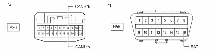
*1 DLC3 - - *a Front view of wire harness connector
(to No. 1 Global CAN Junction Connector)*b to Hybrid Vehicle Control ECU Standard Resistance
Tester Connection Condition Specified Condition A93-8 (CANH) - H56-16 (BAT) Cable disconnected from negative (-) auxiliary battery terminal 6 kΩ or higher A93-19 (CANL) - H56-16 (BAT) Result
Proceed to OK NG
Result:
NG
See step 17
Result:
OK
See step 14
- CHECK FOR SHORT TO +B IN CAN BUS LINE (NO. 1 GLOBAL CAN JUNCTION CONNECTOR - ECM)
- Measure the resistance according to the value(s) in the table below.
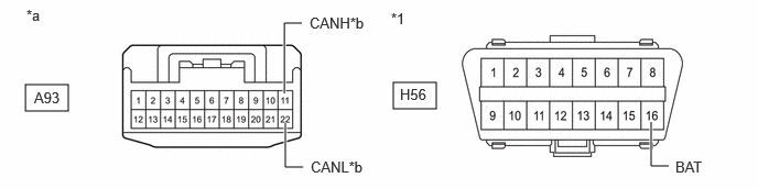
*1 DLC3 - - *a Front view of wire harness connector
(to No. 1 Global CAN Junction Connector)*b to ECM Standard Resistance
Tester Connection Condition Specified Condition A93-9 (CANH) - H56-16 (BAT) Cable disconnected from negative (-) auxiliary battery terminal 6 kΩ or higher A93-20 (CANL) - H56-16 (BAT) Result
Proceed to OK NG
Result:
NG
See step 18
Result:
OK
See step 15
- Measure the resistance according to the value(s) in the table below.
- CHECK FOR SHORT TO +B IN CAN BUS LINE (NO. 1 GLOBAL CAN JUNCTION CONNECTOR - NO. 1 SKID CONTROL ECU (BRAKE BOOSTER WITH MASTER CYLINDER ASSEMBLY))
- Measure the resistance according to the value(s) in the table below.
*1 DLC3 - - *a Front view of wire harness connector
(to No. 1 Global CAN Junction Connector)*b to No. 1 Skid Control ECU (Brake Booster with Master Cylinder Assembly) Standard Resistance
Tester Connection Condition Specified Condition A93-10 (CANH) - H56-16 (BAT) Cable disconnected from negative (-) auxiliary battery terminal 6 kΩ or higher A93-21 (CANL) - H56-16 (BAT) Result
Proceed to OK NG
Result:
NG
See step 19
Result:
OK
See step 16
- Measure the resistance according to the value(s) in the table below.
- CHECK FOR SHORT TO +B IN CAN BUS LINE (NO. 1 GLOBAL CAN JUNCTION CONNECTOR - NO. 2 SKID CONTROL ECU (BRAKE ACTUATOR ASSEMBLY))
- Measure the resistance according to the value(s) in the table below.
*1 DLC3 - - *a Front view of wire harness connector
(to No. 1 Global CAN Junction Connector)*b to No. 2 Skid Control ECU (Brake Actuator Assembly) Standard Resistance
Tester Connection Condition Specified Condition A93-11 (CANH) - H56-16 (BAT) Cable disconnected from negative (-) auxiliary battery terminal 6 kΩ or higher A93-22 (CANL) - H56-16 (BAT) Result
Proceed to OK NG
Result:
OK
REPLACE NO. 1 GLOBAL CAN JUNCTION CONNECTOR
Result:
NG
See step 20
- Measure the resistance according to the value(s) in the table below.
- CHECK FOR SHORT TO +B IN CAN BUS LINE (NO. 1 GLOBAL CAN JUNCTION CONNECTOR - HYBRID VEHICLE CONTROL ECU)
- Disconnect the H67 hybrid vehicle control ECU connector.
- Measure the resistance according to the value(s) in the table below.
*1 DLC3 - - *a Front view of wire harness connector
(to No. 1 Global CAN Junction Connector)*b to Hybrid Vehicle Control ECU Standard Resistance
Tester Connection Condition Specified Condition A93-8 (CANH) - H56-16 (BAT) Cable disconnected from negative (-) auxiliary battery terminal 6 kΩ or higher A93-19 (CANL) - H56-16 (BAT) Result
Proceed to OK NG
Result:
OK
REPLACE HYBRID VEHICLE CONTROL ECU
Refer to REMOVAL [11/2023 - ]
Result:
NG
REPAIR OR REPLACE CAN MAIN BUS LINE OR CONNECTOR (NO. 1 GLOBAL CAN JUNCTION CONNECTOR - HYBRID VEHICLE CONTROL ECU)
- CHECK FOR SHORT TO +B IN CAN BUS LINE (NO. 1 GLOBAL CAN JUNCTION CONNECTOR - ECM)
- Disconnect the A27 ECM connector.
- Measure the resistance according to the value(s) in the table below.
*1 DLC3 - - *a Front view of wire harness connector
(to No. 1 Global CAN Junction Connector)*b to ECM Standard Resistance
Tester Connection Condition Specified Condition A93-9 (CANH) - H56-16 (BAT) Cable disconnected from negative (-) auxiliary battery terminal 6 kΩ or higher A93-20 (CANL) - H56-16 (BAT) Result
Proceed to OK NG
Result:
OK
REPLACE ECM
Refer to REMOVAL [11/2023 - ]
Result:
NG
REPAIR OR REPLACE CAN BRANCH LINE OR CONNECTOR (NO. 1 GLOBAL CAN JUNCTION CONNECTOR - ECM)
- CHECK FOR SHORT TO +B IN CAN BUS LINE (NO. 1 GLOBAL CAN JUNCTION CONNECTOR - NO. 1 SKID CONTROL ECU (BRAKE BOOSTER WITH MASTER CYLINDER ASSEMBLY))
- Disconnect the A44 No. 1 skid control ECU (brake booster with master cylinder assembly) connector.
- Measure the resistance according to the value(s) in the table below.
*1 DLC3 - - *a Front view of wire harness connector
(to No. 1 Global CAN Junction Connector)*b to No. 1 Skid Control ECU (Brake Booster with Master Cylinder Assembly) Standard Resistance
Tester Connection Condition Specified Condition A93-10 (CANH) - H56-16 (BAT) Cable disconnected from negative (-) auxiliary battery terminal 6 kΩ or higher A93-21 (CANL) - H56-16 (BAT) Result
Proceed to OK NG
Result:
OK
REPLACE NO. 1 SKID CONTROL ECU (BRAKE BOOSTER WITH MASTER CYLINDER ASSEMBLY)
Refer to REMOVAL [11/2023 - ]
Result:
NG
REPAIR OR REPLACE CAN BRANCH LINE OR CONNECTOR (NO. 1 GLOBAL CAN JUNCTION CONNECTOR - NO. 1 SKID CONTROL ECU (BRAKE BOOSTER WITH MASTER CYLINDER ASSEMBLY))
- CHECK FOR SHORT TO +B IN CAN BUS LINE (NO. 1 GLOBAL CAN JUNCTION CONNECTOR - NO. 2 SKID CONTROL ECU (BRAKE ACTUATOR ASSEMBLY))
- Disconnect the A57 No. 2 skid control ECU (brake actuator assembly) connector.
- Measure the resistance according to the value(s) in the table below.
*1 DLC3 - - *a Front view of wire harness connector
(to No. 1 Global CAN Junction Connector)*b to No. 2 Skid Control ECU (Brake Actuator Assembly) Standard Resistance
Tester Connection Condition Specified Condition A93-11 (CANH) - H56-16 (BAT) Cable disconnected from negative (-) auxiliary battery terminal 6 kΩ or higher A93-22 (CANL) - H56-16 (BAT) Result
Proceed to OK NG
Result:
OK
REPLACE NO. 2 SKID CONTROL ECU (BRAKE ACTUATOR ASSEMBLY)
Refer to REMOVAL [11/2023 - ]
Result:
NG
REPAIR OR REPLACE CAN MAIN BUS LINE OR CONNECTOR (NO. 1 GLOBAL CAN JUNCTION CONNECTOR - NO. 2 SKID CONTROL ECU (BRAKE ACTUATOR ASSEMBLY))
- CHECK FOR SHORT IN CAN BUS LINES (NO. 1 GLOBAL CAN JUNCTION CONNECTOR - HYBRID VEHICLE CONTROL ECU)
- Disconnect the A93 No. 1 global CAN junction connector.
- Measure the resistance according to the value(s) in the table below.
*a Front view of wire harness connector
(to No. 1 Global CAN Junction Connector)*b to Hybrid Vehicle Control ECU Standard Resistance
Tester Connection Condition Specified Condition A93-8 (CANH) - A93-19 (CANL) Cable disconnected from negative (-) auxiliary battery terminal 108 to 132 Ω Result
Proceed to OK NG
Result:
NG
See step 25
Result:
OK
See step 22
- CHECK FOR SHORT IN CAN BUS LINES (NO. 1 GLOBAL CAN JUNCTION CONNECTOR - ECM)
- Measure the resistance according to the value(s) in the table below.
*a Front view of wire harness connector
(to No. 1 Global CAN Junction Connector)*b to ECM Standard Resistance
Tester Connection Condition Specified Condition A93-9 (CANH) - A93-20 (CANL) Cable disconnected from negative (-) auxiliary battery terminal 200 Ω or higher Result
Proceed to OK NG
Result:
NG
See step 26
Result:
OK
See step 23
- Measure the resistance according to the value(s) in the table below.
- CHECK FOR SHORT IN CAN BUS LINES (NO. 1 GLOBAL CAN JUNCTION CONNECTOR - NO. 1 SKID CONTROL ECU (BRAKE BOOSTER WITH MASTER CYLINDER ASSEMBLY))
- Measure the resistance according to the value(s) in the table below.
*a Front view of wire harness connector
(to No. 1 Global CAN Junction Connector)*b to No. 1 Skid Control ECU (Brake Booster with Master Cylinder Assembly) Standard Resistance
Tester Connection Condition Specified Condition A93-10 (CANH) - A93-21 (CANL) Cable disconnected from negative (-) auxiliary battery terminal 200 Ω or higher Result
Proceed to OK NG
Result:
NG
See step 27
Result:
OK
See step 24
- Measure the resistance according to the value(s) in the table below.
- CHECK FOR SHORT IN CAN BUS LINES (NO. 1 GLOBAL CAN JUNCTION CONNECTOR - NO. 2 SKID CONTROL ECU (BRAKE ACTUATOR ASSEMBLY))
- Measure the resistance according to the value(s) in the table below.
*a Front view of wire harness connector
(to No. 1 Global CAN Junction Connector)*b to No. 2 Skid Control ECU (Brake Actuator Assembly) Standard Resistance
Tester Connection Condition Specified Condition A93-11 (CANH) - A93-22 (CANL) Cable disconnected from negative (-) auxiliary battery terminal 108 to 132 Ω Result
Proceed to OK NG
Result:
OK
REPLACE NO. 1 GLOBAL CAN JUNCTION CONNECTOR
Result:
NG
See step 28
- Measure the resistance according to the value(s) in the table below.
- CHECK FOR SHORT IN CAN BUS LINES (NO. 1 GLOBAL CAN JUNCTION CONNECTOR - HYBRID VEHICLE CONTROL ECU)
- Disconnect the H67 hybrid vehicle control ECU connector.
- Measure the resistance according to the value(s) in the table below.
*a Front view of wire harness connector
(to No. 1 Global CAN Junction Connector)*b to Hybrid Vehicle Control ECU Standard Resistance
Tester Connection Condition Specified Condition A93-8 (CANH) - A93-19 (CANL) Cable disconnected from negative (-) auxiliary battery terminal 1 MΩ or higher Result
Proceed to OK NG
Result:
OK
REPLACE HYBRID VEHICLE CONTROL ECU
Refer to REMOVAL [11/2023 - ]
Result:
NG
REPAIR OR REPLACE CAN MAIN BUS LINES OR CONNECTOR (NO. 1 GLOBAL CAN JUNCTION CONNECTOR - HYBRID VEHICLE CONTROL ECU)
- CHECK FOR SHORT IN CAN BUS LINES (NO. 1 GLOBAL CAN JUNCTION CONNECTOR - ECM)
- Disconnect the A27 ECM connector.
- Measure the resistance according to the value(s) in the table below.
*a Front view of wire harness connector
(to No. 1 Global CAN Junction Connector)*b to ECM Standard Resistance
Tester Connection Condition Specified Condition A93-9 (CANH) - A93-20 (CANL) Cable disconnected from negative (-) auxiliary battery terminal 1 MΩ or higher Result
Proceed to OK NG
Result:
OK
REPLACE ECM
Refer to REMOVAL [11/2023 - ]
Result:
NG
REPAIR OR REPLACE CAN BRANCH LINES OR CONNECTOR (NO. 1 GLOBAL CAN JUNCTION CONNECTOR - ECM)
- CHECK FOR SHORT IN CAN BUS LINES (NO. 1 GLOBAL CAN JUNCTION CONNECTOR - NO. 1 SKID CONTROL ECU (BRAKE BOOSTER WITH MASTER CYLINDER ASSEMBLY))
- Disconnect the A44 No. 1 skid control ECU (brake booster with master cylinder assembly) connector.
- Measure the resistance according to the value(s) in the table below.
*a Front view of wire harness connector
(to No. 1 Global CAN Junction Connector)*b to No. 1 Skid Control ECU (Brake Booster with Master Cylinder Assembly) Standard Resistance
Tester Connection Condition Specified Condition A93-10 (CANH) - A93-21 (CANL) Cable disconnected from negative (-) auxiliary battery terminal 1 MΩ or higher Result
Proceed to OK NG
Result:
OK
REPLACE NO. 1 SKID CONTROL ECU (BRAKE BOOSTER WITH MASTER CYLINDER ASSEMBLY)
Refer to REMOVAL [11/2023 - ]
Result:
NG
REPAIR OR REPLACE CAN BRANCH LINES OR CONNECTOR (NO. 1 GLOBAL CAN JUNCTION CONNECTOR - NO. 1 SKID CONTROL ECU (BRAKE BOOSTER WITH MASTER CYLINDER ASSEMBLY))
- CHECK FOR SHORT IN CAN BUS LINES (NO. 1 GLOBAL CAN JUNCTION CONNECTOR - NO. 2 SKID CONTROL ECU (BRAKE ACTUATOR ASSEMBLY))
- Disconnect the A57 No. 2 skid control ECU (brake actuator assembly) connector.
- Measure the resistance according to the value(s) in the table below.
*a Front view of wire harness connector
(to No. 1 Global CAN Junction Connector)*b to No. 2 Skid Control ECU (Brake Actuator Assembly) Standard Resistance
Tester Connection Condition Specified Condition A93-11 (CANH) - A93-22 (CANL) Cable disconnected from negative (-) auxiliary battery terminal 1 MΩ or higher Result
Proceed to OK NG
Result:
OK
REPLACE NO. 2 SKID CONTROL ECU (BRAKE ACTUATOR ASSEMBLY)
Refer to REMOVAL [11/2023 - ]
Result:
NG
REPAIR OR REPLACE CAN MAIN BUS LINES OR CONNECTOR (NO. 1 GLOBAL CAN JUNCTION CONNECTOR - NO. 2 SKID CONTROL ECU (BRAKE ACTUATOR ASSEMBLY))
- CHECK FOR OPEN IN CAN MAIN BUS LINES (HYBRID VEHICLE CONTROL ECU)
- Disconnect the H67 hybrid vehicle control ECU connector.
- Measure the resistance according to the value(s) in the table below.
*a Front view of wire harness connector
(to Hybrid Vehicle Control ECU)Standard Resistance
Tester Connection Condition Specified Condition H67-24 (CA3P) - H67-11 (CA3N) Cable disconnected from negative (-) auxiliary battery terminal 108 to 132 Ω Result
Proceed to OK NG
Result:
OK
REPLACE HYBRID VEHICLE CONTROL ECU
Refer to REMOVAL [11/2023 - ]
Result:
NG
See step 30
- CHECK FOR OPEN IN CAN MAIN BUS LINES (NO. 1 GLOBAL CAN JUNCTION CONNECTOR - HYBRID VEHICLE CONTROL ECU)
- Reconnect the H67 hybrid vehicle control ECU connector.
- Disconnect the A93 No. 1 global CAN junction connector.
- Measure the resistance according to the value(s) in the table below.
*a Front view of wire harness connector
(to No. 1 Global CAN Junction Connector)*b to Hybrid Vehicle Control ECU Standard Resistance
Tester Connection Condition Specified Condition A93-8 (CANH) - A93-19 (CANL) Cable disconnected from negative (-) auxiliary battery terminal 108 to 132 Ω Result
Proceed to OK NG
Result:
NG
REPAIR OR REPLACE CAN MAIN BUS LINES OR CONNECTOR (NO. 1 GLOBAL CAN JUNCTION CONNECTOR - HYBRID VEHICLE CONTROL ECU)
Result:
OK
See step 31
- CHECK FOR OPEN IN CAN MAIN BUS LINES (NO. 1 GLOBAL CAN JUNCTION CONNECTOR - NO. 2 SKID CONTROL ECU (BRAKE ACTUATOR ASSEMBLY))
- Measure the resistance according to the value(s) in the table below.
*a Front view of wire harness connector
(to No. 1 Global CAN Junction Connector)*b to No. 2 Skid Control ECU (Brake Actuator Assembly) Standard Resistance
Tester Connection Condition Specified Condition A93-11 (CANH) - A93-22 (CANL) Cable disconnected from negative (-) auxiliary battery terminal 108 to 132 Ω Result
Proceed to OK NG
Result:
OK
REPLACE NO. 1 GLOBAL CAN JUNCTION CONNECTOR
Result:
NG
See step 32
- Measure the resistance according to the value(s) in the table below.
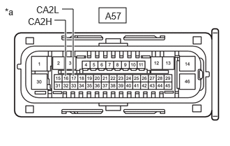
- CHECK FOR OPEN IN CAN MAIN BUS LINES (NO. 1 SKID CONTROL ECU (BRAKE BOOSTER WITH MASTER CYLINDER ASSEMBLY))
- Reconnect the A93 No. 1 global CAN junction connector.
- Disconnect the A57 No. 2 skid control ECU (brake actuator assembly) connector.
- Measure the resistance according to the value(s) in the table below.
*a Front view of wire harness connector
(to No. 2 Skid Control ECU (Brake Actuator Assembly))Standard Resistance
Tester Connection Condition Specified Condition A57-16 (CA2H) - A57-17 (CA2L) Cable disconnected from negative (-) auxiliary battery terminal 108 to 132 Ω Result
Proceed to OK NG
Result:
OK
REPLACE NO. 2 SKID CONTROL ECU (BRAKE ACTUATOR ASSEMBLY)
Refer to REMOVAL [11/2023 - ]
Result:
NG
REPAIR OR REPLACE CAN MAIN BUS LINES OR CONNECTOR (NO. 1 SKID CONTROL ECU (BRAKE BOOSTER WITH MASTER CYLINDER ASSEMBLY) - NO. 1 GLOBAL CAN JUNCTION CONNECTOR)