Brake Booster (Skid Control ECU) Communication Stop Mode [12/2019 - 11/2023]: Procedure
WARNING: This page is about a different variant/trim than selected.
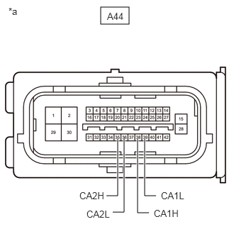
- CHECK FOR OPEN IN CAN BUS LINES (NO. 1 SKID CONTROL ECU (BRAKE BOOSTER WITH MASTER CYLINDER ASSEMBLY) BRANCH LINE)
- Disconnect the cable from the negative (-) auxiliary battery terminal.
- Disconnect the A44 No. 1 skid control ECU (brake booster with master cylinder assembly) connector.
- Measure the resistance according to the value(s) in the table below.
Standard Resistance
Tester Connection Condition Specified Condition A44-38 (CA1H) - A44-39 (CA1L) Cable disconnected from negative (-) auxiliary battery terminal 54 to 69 Ω A44-35 (CA2H) - A44-36 (CA2L) Cable disconnected from negative (-) auxiliary battery terminal 54 to 69 Ω *a Front view of wire harness connector
(to No. 1 Skid Control ECU (Brake Booster with Master Cylinder Assembly))Result
Result OK NG
Result:
NG
REPAIR OR REPLACE CAN BRANCH LINES OR CONNECTOR (NO. 1 SKID CONTROL ECU (BRAKE BOOSTER WITH MASTER CYLINDER ASSEMBLY))
Result:
OK
See step 2
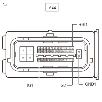
- CHECK HARNESS AND CONNECTOR (POWER SOURCE CIRCUIT)
- Measure the resistance according to the value(s) in the table below.
Standard Resistance
Tester Connection Condition Specified Condition A44-28 (GND1) - Body ground Cable disconnected from negative (-) auxiliary battery terminal Below 1 Ω *a Front view of wire harness connector
(to No. 1 Skid Control ECU (Brake Booster with Master Cylinder Assembly)) - Reconnect the cable to the negative (-) auxiliary battery terminal.
- Measure the voltage according to the value(s) in the table below.
Standard Voltage
Tester Connection Condition Specified Condition A44-14 (+BI1) - Body ground Ignition switch off 11 to 14 V A44-31 (IG1) - Body ground Ignition switch ON 11 to 14 V A44-42 (IG2) - Body ground Ignition switch ON 11 to 14 V Result
Result OK NG
Result:
OK
REPLACE NO. 1 SKID CONTROL ECU (BRAKE BOOSTER WITH MASTER CYLINDER ASSEMBLY)
Refer to REMOVAL [12/2019 - 10/2022] , or refer to REMOVAL [10/2022 - 11/2023]
Result:
NG
REPAIR OR REPLACE HARNESS OR CONNECTOR (POWER SOURCE CIRCUIT)
- Measure the resistance according to the value(s) in the table below.