Main Body ECU Communication Stop Mode [11/2023 - ]: Procedure
WARNING: This page is about a different variant/trim than selected.
- CHECK FOR OPEN IN CAN BUS LINES (MAIN BODY ECU (MULTIPLEX NETWORK BODY ECU) MAIN LINE)
- Disconnect the cable from the negative (-) auxiliary battery terminal.
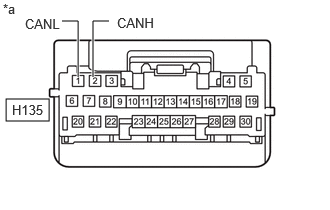
- Disconnect the H135 main body ECU (multiplex network body ECU) connector.
- Measure the resistance according to the value(s) in the table below.
Standard Resistance
Tester Connection Condition Specified Condition H135-2 (CANH) - H135-1 (CANL) Cable disconnected from negative (-) auxiliary battery terminal 108 to 132 Ω *a Front view of wire harness connector
(to Main Body ECU (Multiplex Network Body ECU))Result
Proceed to OK NG
Result:
NG
REPAIR OR REPLACE CAN MAIN BUS LINES OR CONNECTOR (MAIN BODY ECU (MULTIPLEX NETWORK BODY ECU))
Result:
OK
See step 2
- CHECK HARNESS AND CONNECTOR (POWER SOURCE CIRCUIT)
- Remove the main body ECU (multiplex network body ECU).
Refer to REMOVAL [11/2023 - ]
- Reconnect the cable to the negative (-) auxiliary battery terminal.
- Measure the voltage according to the value(s) in the table below.
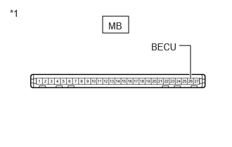
*1 Power Distribution Box Assembly Standard Voltage
Tester Connection Condition Specified Condition MB-26 (BECU) - Body ground Ignition switch off 11 to 14 V NOTE:Perform this inspection with the wire harness connected to the power distribution box assembly.
Result
Proceed to OK NG
Result:
OK
CHECK ECU POWER SOURCE CIRCUIT
Refer to IG Signal Circuit [11/2023 - ]
Result:
NG
See step 3
- Remove the main body ECU (multiplex network body ECU).
- CHECK HARNESS AND CONNECTOR (BECU SIGNAL CIRCUIT)
- Disconnect the cable from the negative (-) auxiliary battery terminal.
- Disconnect the 8E power distribution box assembly connector.
- Reconnect the cable to the negative (-) auxiliary battery terminal.
- Measure the voltage according to the value(s) in the table below.
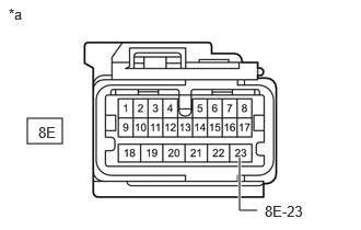
*a Front view of wire harness connector
(to Power Distribution Box Assembly)Standard Voltage
Tester Connection Condition Specified Condition 8E-23 - Body ground Ignition switch off 11 to 14 V Result
Proceed to OK NG
Result:
OK
REPLACE POWER DISTRIBUTION BOX ASSEMBLY
Refer to REMOVAL [11/2023 - ]
Result:
NG
REPAIR OR REPLACE HARNESS OR CONNECTOR (BECU SIGNAL CIRCUIT)