Mute Signal Circuit between Radio Receiver and Stereo Component Amplifier [12/2019 - 10/2022]: Procedure
- INSPECT STEREO COMPONENT AMPLIFIER ASSEMBLY
- Measure the voltage according to the value(s) in the table below.
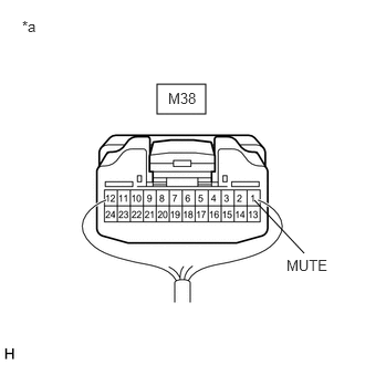
*a Component with harness connected
(Stereo Component Amplifier Assembly)Standard Voltage
Tester Connection Condition Specified Condition M38-1 (MUTE) - Body ground Ignition switch ACC, audio system playing
→ Changing modes2 V or higher
→ Below 1 VResult
Proceed to OK NG
Result:
OK
PROCEED TO NEXT SUSPECTED AREA SHOWN IN PROBLEM SYMPTOMS TABLE. Refer to PROBLEM SYMPTOMS TABLE [12/2019 - 10/2022]
Result:
NG
See step 2
- Measure the voltage according to the value(s) in the table below.
- CHECK HARNESS AND CONNECTOR (RADIO AND DISPLAY RECEIVER ASSEMBLY - STEREO COMPONENT AMPLIFIER ASSEMBLY)
- Disconnect the H1 radio and display receiver assembly connector.
- Disconnect the M38 stereo component amplifier assembly connector.
- Measure the resistance according to the value(s) in the table below.
Standard Resistance
Tester Connection Condition Specified Condition H1-25 (MUT1) - M38-1 (MUTE) Always Below 1 Ω H1-25 (MUT1) or M38-1 (MUTE) - Body ground Always 10 kΩ or higher Result
Proceed to OK NG
Result:
NG
REPAIR OR REPLACE HARNESS OR CONNECTOR
Result:
OK
See step 3
- INSPECT STEREO COMPONENT AMPLIFIER ASSEMBLY (OUTPUT SIGNAL)
- Reconnect the M38 stereo component amplifier assembly connector.
- Measure the voltage according to the value(s) in the table below.
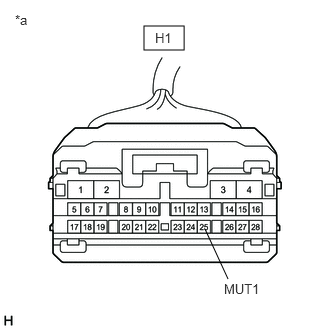
*a Front view of wire harness connector
(to Radio and Display Receiver Assembly)Standard Voltage
Tester Connection Condition Specified Condition H1-25 (MUT1) - Body ground Ignition switch ACC, audio system is playing 2 V or higher Result
Proceed to OK NG
Result:
OK
REPLACE RADIO AND DISPLAY RECEIVER ASSEMBLY. Refer to REMOVAL [12/2019 - 10/2022]
Result:
NG
REPLACE STEREO COMPONENT AMPLIFIER ASSEMBLY. Refer to REMOVAL [12/2019 - ]