Terminals Of Ecu [11/2023 - ]
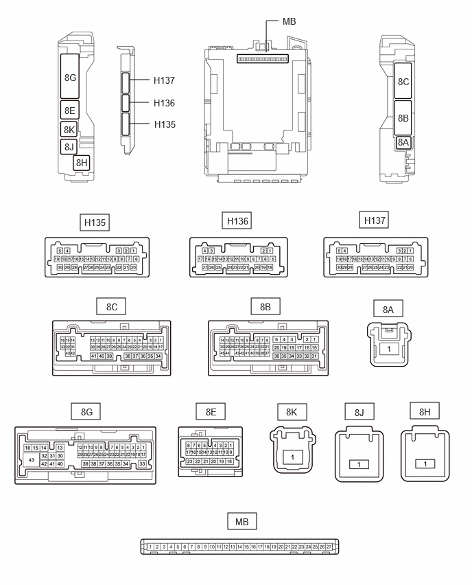
- CHECK MAIN BODY ECU (MULTIPLEX NETWORK BODY ECU) AND POWER DISTRIBUTION BOX ASSEMBLY
- Disconnect the power distribution box assembly and main body ECU (multiplex network body ECU) connectors.
- Measure the voltage and resistance according to the value(s) in the table below.
Terminal No. (Symbol) Terminal Description Condition Specified Condition 8B-36 - Body ground Ground Always Below 1 Ω 8B-44 - Body ground Ground Always Below 1 Ω 8C-41 - Body ground Ground Always Below 1 Ω 8C-25 - Body ground Ground Always Below 1 Ω 8E-13 - Body ground Auxiliary battery power supply Ignition switch off 11 to 14 V 8E-23 - Body ground Auxiliary battery power supply Ignition switch off 11 to 14 V 8K-1 - Body ground Auxiliary battery power supply Ignition switch off 11 to 14 V 8H-1 - Body ground Auxiliary battery power supply Ignition switch off 11 to 14 V 8J-1 - Body ground Auxiliary battery power supply Ignition switch off 11 to 14 V - Connect the power distribution box assembly and main body ECU (multiplex network body ECU) connectors.
- Measure the voltage and check for pulses according to the value(s) in the table below.
Terminal No. (Symbol) Terminal Description Condition Specified Condition 8B-29 - Body ground*1 R shift position switch signal Ignition switch off, reverse (R) not selected Below 1 V Ignition switch ON, reverse (R) selected 11 to 14 V 8E-3 - Body ground Daytime running light system drive output Daytime running light system operating Below 1 V Daytime running light system not operating 11 to 14 V 8E-6 - Body ground H-LP LH relay drive output - 15 seconds or more after ignition switch turned off
- Taillights off
9.5 to 14 V - Ignition switch ON or within 15 seconds after ignition switch turned off
- Taillights on
Below 1 V 8E-10 - Body ground H-LP RH relay drive output - 15 seconds or more after ignition switch turned off
- Taillights off
9.5 to 14 V - Ignition switch ON or within 15 seconds after ignition switch turned off
- Taillights on
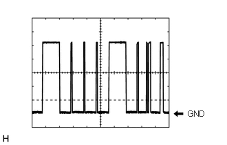
Below 1 V 8E-18 - Body ground Taillights drive output Ignition switch off Below 1 V Ignition switch ON 11 to 14 V 8G-30 - Body ground Taillights drive output Taillights off Below 1 V Taillights on 11 to 14 V 8G-28 - Body ground*2 Front fog lights drive output Taillights on, fog light switch in off position Below 1 V Taillights on, fog light switch in front position 11 to 14 V 8G-38 - Body ground*1 Back-up lights drive output Ignition switch ON, reverse (R) not selected Below 1 V Ignition switch ON, reverse (R) selected 11 to 14 V H135-8 (CLTB) - H135-21 (CLTE) Automatic light control sensor power supply output Ignition switch ON 11 to 14 V H135-14 (AHBI) - Body ground Auto high beam switch signal input Auto high beam switch off 11 to 14 V Auto high beam switch on Below 1 V H135-15 (AHID) - Body ground Auto high beam switch indicator drive output Ignition switch ON, auto high beam switch off 11 to 14 V Ignition switch ON, auto high beam switch on Below 1 V H135-20 (CLTS) - Body ground Automatic light control sensor signal input Ignition switch ON Pulse generation (See waveform 1) H135-22 (DIM) - Body ground High beam headlight drive output Light control switch in head position and dimmer switch in high or high flash position Below 1 V Dimmer switch not in high or high flash position 11 to 14 V H135-26 (HEAD) - Body ground Light control switch head position input Light control switch not in head position 11 to 14 V Light control switch in head position Below 1 V - *1: for HV Model
- *2: w/ Front Fog Light
- CHECK COMBINATION METER ASSEMBLY
for 12.3 Inch Display: Refer to TERMINALS OF ECU [11/2023 - ]
except 12.3 Inch Display: Refer to TERMINALS OF ECU [11/2023 - ]
- CHECK FORWARD RECOGNITION CAMERA
Refer to TERMINALS OF ECU [12/2019 - ]
- CHECK STEERING SENSOR
for HV Model: Refer to TERMINALS OF ECU [11/2023 - 11/2024] , or refer to TERMINALS OF ECU [11/2024 - ]
for Gasoline Model: Refer to TERMINALS OF ECU [11/2023 - ]