DTC B1244-00: Light Sensor Circuit Malfunction [11/2023 - ]: Procedure
- CLEAR DTC
Result:
NEXT
See step 2
- CHECK FOR DTC
- Turn the ignition switch to ON.
- Wait 10 seconds or more.
- Check for DTCs.
Body Electrical > Main Body > Trouble Codes
OK
DTC B1244-00 is not output.
Result
Proceed to OK NG
Result:
OK
USE SIMULATION METHOD TO CHECK. Refer to HOW TO PROCEED WITH TROUBLESHOOTING [12/2019 - ]
Result:
NG
See step 3
- READ VALUE USING GTS
- According to the display on the GTS, read the Data List and check that the value of Light Sensor Illuminance changes while performing the following:
- Cover the automatic light control sensor with an opaque object.
- Slowly move the opaque object to uncover and then cover the automatic light control sensor.
Body Electrical > Main Body > Data List
Tester Display Measurement Item Range Normal Condition Diagnostic Note Light Sensor Illuminance Automatic light control sensor illuminance 0 to 8191 or SensorFail Value is output according to ambient light level The displayed value is "0" when no light is detected. Body Electrical > Main Body > Data List
Tester Display Light Sensor Illuminance OK
The value changes according to the amount the automatic light control sensor is covered.
Result
Proceed to OK NG
Result:
OK
REPLACE MAIN BODY ECU (MULTIPLEX NETWORK BODY ECU). Refer to REMOVAL [11/2023 - ]
Result:
NG
See step 4
- According to the display on the GTS, read the Data List and check that the value of Light Sensor Illuminance changes while performing the following:
- CHECK HARNESS AND CONNECTOR (AUTOMATIC LIGHT CONTROL SENSOR - MAIN BODY ECU (MULTIPLEX NETWORK BODY ECU))
- Disconnect the G5 automatic light control sensor connector.
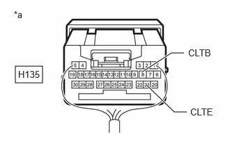
- Disconnect the H135 main body ECU (multiplex network body ECU) connector.
- Measure the resistance according to the value(s) in the table below.
Standard Resistance
Tester Connection Condition Specified Condition G5-1 (CLTB) - H135-8 (CLTB) Always Below 1 Ω G5-4 (CLTS) - H135-20 (CLTS) Always Below 1 Ω G5-2 (CLTE) - H135-21 (CLTE) Always Below 1 Ω G5-1 (CLTB) or H135-8 (CLTB) - Body ground Always 10 kΩ or higher G5-4 (CLTS) or H135-20 (CLTS) - Body ground Always 10 kΩ or higher G5-2 (CLTE) or H135-21 (CLTE) - Body ground Always 10 kΩ or higher Result
Proceed to OK NG
Result:
NG
REPAIR OR REPLACE HARNESS OR CONNECTOR
Result:
OK
See step 5
- CHECK MAIN BODY ECU (MULTIPLEX NETWORK BODY ECU)
*a Component with harness connected
(Main Body ECU (Multiplex Network Body ECU))- Connect the H135 main body ECU (multiplex network body ECU) connector.
- Measure the voltage according to the value(s) in the table below.
Standard Voltage
Tester Connection Switch Condition Specified Condition H135-8 (CLTB) - H135-21 (CLTE) Ignition switch ON 11 to 14 V Result
Proceed to OK NG
Result:
NG
REPLACE MAIN BODY ECU (MULTIPLEX NETWORK BODY ECU). Refer to REMOVAL [11/2023 - ]
Result:
OK
See step 6
- INSPECT AUTOMATIC LIGHT CONTROL SENSOR
Refer to ON-VEHICLE INSPECTION [12/2019 - ]
Result
Proceed to OK NG Result:
OK
REPLACE MAIN BODY ECU (MULTIPLEX NETWORK BODY ECU). Refer to REMOVAL [11/2023 - ]
Result:
NG
REPLACE AUTOMATIC LIGHT CONTROL SENSOR. Refer to REMOVAL [12/2019 - ]