DTC U0235-87: Lost Communication with Cruise Control Front Distance Range Sensor Single Sensor or Center Missing Message [09/2020 - 11/2023]: Procedure
- CHECK FOR DTCs
- Using the GTS, check for front radar sensor system DTCs.
Body Electrical > Front Radar Sensor > Trouble Codes
Result
Result Proceed to DTC U0104-87 is output A DTC U0104-87 is not output B
Result:
B
See step 4
Result:
A
See step 2
- Using the GTS, check for front radar sensor system DTCs.
- CHECK CAN BUS LINES
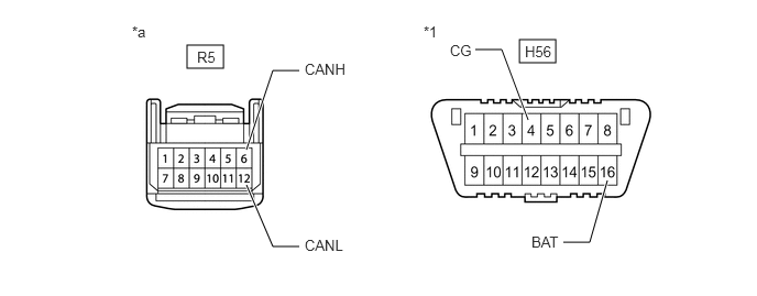
*1 DLC3 - - *a Front view of wire harness connector
(to Forward Recognition Camera)- - - Disconnect the R5 forward recognition camera connector.
- Measure the resistance according to the value(s) in the table below.
Standard Resistance
Tester Connection Condition Specified Condition R5-6 (CANH) - R5-12 (CANL) Cable disconnected from negative (-) auxiliary battery terminal 108 to 132 Ω - Measure the resistance according to the value(s) in the table below.
Standard Resistance
Tester Connection Condition Specified Condition R5-6 (CANH) - H56-4 (CG) Cable disconnected from negative (-) auxiliary battery terminal 200 Ω or higher R5-12 (CANL) - H56-4 (CG) Cable disconnected from negative (-) auxiliary battery terminal 200 Ω or higher R5-6 (CANH) - H56-16 (BAT) Cable disconnected from negative (-) auxiliary battery terminal 6 kΩ or higher R5-12 (CANL) - H56-16 (BAT) Cable disconnected from negative (-) auxiliary battery terminal 6 kΩ or higher - Connect the R5 forward recognition camera connector.
Result
Proceed to OK NG
Result:
OK
REPLACE FORWARD RECOGNITION CAMERA. Refer to REMOVAL [09/2020 - 11/2023]
Result:
NG
See step 3
- CHECK CAN BUS LINES
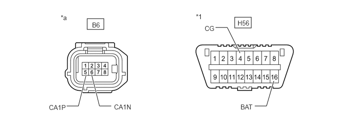
*1 DLC3 - - *a Front view of wire harness connector
(to Millimeter Wave Radar Sensor Assembly)- - - Disconnect the B6 millimeter wave radar sensor assembly connector.
- Measure the resistance according to the value(s) in the table below.
Standard Resistance
Tester Connection Condition Specified Condition B6-5 (CA1P) - B6-6 (CA1N) Cable disconnected from negative (-) auxiliary battery terminal 108 to 132 Ω - Measure the resistance according to the value(s) in the table below.
Standard Resistance
Tester Connection Condition Specified Condition B6-5 (CA1P) - H56-4 (CG) Cable disconnected from negative (-) auxiliary battery terminal 200 Ω or higher B6-6 (CA1N) - H56-4 (CG) Cable disconnected from negative (-) auxiliary battery terminal 200 Ω or higher B6-5 (CA1P) - H56-16 (BAT) Cable disconnected from negative (-) auxiliary battery terminal 6 kΩ or higher B6-6 (CA1N) - H56-16 (BAT) Cable disconnected from negative (-) auxiliary battery terminal 6 kΩ or higher - Connect the B6 millimeter wave radar sensor assembly connector.
Result
Proceed to OK NG
Result:
OK
REPLACE MILLIMETER WAVE RADAR SENSOR ASSEMBLY. Refer to REMOVAL [09/2020 - 11/2023]
Result:
NG
REPAIR OR REPLACE HARNESS OR CONNECTOR
- CHECK CONNECTOR (MILLIMETER WAVE RADAR SENSOR ASSEMBLY)
- Check the locking part and terminals of the millimeter wave radar sensor assembly connector.NOTE:
- Make sure the connector is not loose or disconnected.
- Make sure that the connector and terminals are not deformed or damaged.
OK
The connector and terminals are normal.
Result
Proceed to OK NG
Result:
NG
REPAIR OR REPLACE HARNESS OR CONNECTOR (MILLIMETER WAVE RADAR SENSOR ASSEMBLY)
Result:
OK
See step 5
- Check the locking part and terminals of the millimeter wave radar sensor assembly connector.
- CHECK HARNESS AND CONNECTOR (POWER SOURCE CIRCUIT)
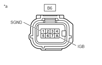
*a Front view of wire harness connector
(to Millimeter Wave Radar Sensor Assembly)- Disconnect the cable from the negative (-) auxiliary battery terminal.
- Disconnect the B6 millimeter wave radar sensor assembly connector.
- Measure the resistance according to the value(s) in the table below.
Standard Resistance
Tester Connection Condition Specified Condition B6-1 (SGND) - Body ground Always Below 1 Ω - Connect the cable to the negative (-) auxiliary battery terminal.
- Measure the voltage according to the value(s) in the table below.
Standard Voltage
Tester Connection Condition Specified Condition B6-8 (IGB) - Body ground Ignition switch ON 11 to 14 V - Connect the B6 millimeter wave radar sensor assembly connector.
Result
Proceed to OK NG
Result:
NG
REPAIR OR REPLACE HARNESS OR CONNECTOR (MILLIMETER WAVE RADAR SENSOR ASSEMBLY POWER SOURCE CIRCUIT)
Result:
OK
See step 6
- INSPECT MILLIMETER WAVE RADAR SENSOR ASSEMBLY (WAVEFORM)
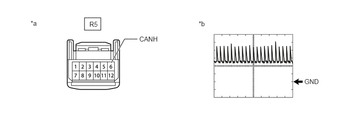
*a Front view of wire harness connector
(to Forward Recognition Camera)*b Waveform - Turn the ignition switch off.
- Disconnect the R5 forward recognition camera connector.
- Turn the ignition switch to ON.
- Using an oscilloscope, measure the waveform at the R5 forward recognition camera connector.
Measurement Condition
Tester Connection Condition Tool Setting R5-6 (CANH) - Body ground Ignition switch ON 1 V/DIV., 100 μs/DIV. NOTE:The oscilloscope waveform is for reference only and does not include noise, fluctuations, etc.
OK
A waveform similar to that in the illustration can be observed.
- Connect the R5 forward recognition camera connector.
Result
Proceed to OK NG
Result:
OK
REPLACE FORWARD RECOGNITION CAMERA. Refer to REMOVAL [09/2020 - 11/2023]
Result:
NG
REPLACE MILLIMETER WAVE RADAR SENSOR ASSEMBLY. Refer to REMOVAL [09/2020 - 11/2023]