Check CAN Communication Connection [11/2023 - ]: Procedure
- CHECK GTS OPERATION
- Connect the GTS to the DLC3 of another vehicle.
- Turn the ignition switch to ON.
- Turn the GTS on.
- Check that the GTS and ECUs can communicate with the ignition switch ON.
HINT:
- ECUs and sensors are not displayed on the "Communication Bus Check" screen when the GTS cannot communicate with the vehicle.
- If communication between the GTS and ECUs is not possible, either the GTS or vehicle has a malfunction.
- If communication between the GTS and ECUs is still not possible even when the GTS is connected to another vehicle, the GTS has a malfunction. Perform the self tests described in the GTS operator's manual. (The GTS may be malfunctioning or its battery may be discharged.)
Result
Result Proceed to OK (Communication between the GTS and the vehicle is not possible but communication is possible when connected to another vehicle.) A NG (Communication is not possible between the GTS and the vehicle, nor between the GTS and another vehicle.) B
Result:
B
REFER TO GTS OPERATOR'S MANUAL
Result:
A
See step 2
- CHECK HARNESS AND CONNECTOR (DLC3 POWER SOURCE CIRCUIT)
- Measure the voltage according to the value(s) in the table below.
Standard Voltage
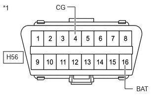
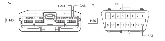
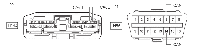
Tester Connection Condition Specified Condition H56-16 (BAT) - Body ground Always 11 to 14 V *1 DLC3 - Disconnect the cable from the negative (-) battery terminal.
- Measure the resistance according to the value(s) in the table below.
Standard Resistance
Tester Connection Condition Specified Condition H56-4 (CG) - Body ground Cable disconnected from negative (-) battery terminal Below 1 Ω Result
Proceed to OK NG
Result:
NG
REPAIR OR REPLACE HARNESS OR CONNECTOR (DLC3 POWER SOURCE CIRCUIT)
Result:
OK
See step 3
- Measure the voltage according to the value(s) in the table below.
- CHECK FOR OPEN IN CAN BUS LINES
- Measure the resistance according to the value(s) in the table below.
*1 DLC3 Standard Resistance
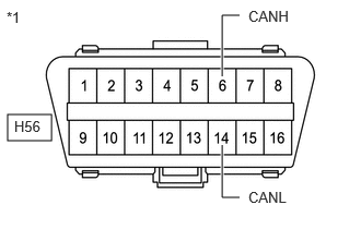
Tester Connection Condition Specified Condition H56-6 (CANH) - H56-14 (CANL) Cable disconnected from negative (-) battery terminal Below 70 Ω Result
Proceed to OK NG
Result:
NG
See step 7
Result:
OK
See step 4
- Measure the resistance according to the value(s) in the table below.
- CHECK FOR SHORT IN CAN BUS LINE
- Measure the resistance according to the value(s) in the table below.
*1 DLC3 Standard Resistance
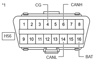
Tester Connection Condition Specified Condition H56-6 (CANH) - H56-14 (CANL) Cable disconnected from negative (-) battery terminal 54 Ω or higher H56-6 (CANH) - H56-4 (CG) Cable disconnected from negative (-) battery terminal 200 Ω or higher H56-14 (CANL) - H56-4 (CG) H56-6 (CANH) - H56-16 (BAT) Cable disconnected from negative (-) battery terminal 6 kΩ or higher H56-14 (CANL) - H56-16 (BAT) Result
Proceed to OK NG
Result:
NG
See step 6
Result:
OK
See step 5
- Measure the resistance according to the value(s) in the table below.
- CHECK FOR HARNESS AND CONNECTOR (POWER SOURCE CIRCUIT)
- Disconnect the H143 central gateway ECU (network gateway ECU) connector.
- Measure the resistance according to the value(s) in the table below.
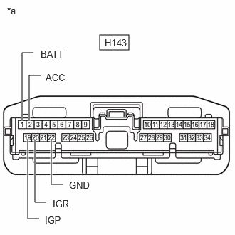
*a Front view of wire harness connector
(to Central Gateway ECU (Network Gateway ECU))Standard Resistance
Tester Connection Condition Specified Condition H143-22 (GND) - Body ground Cable disconnected from negative (-) battery terminal Below 1 Ω - Reconnect the cable to the negative (-) battery terminal.
- Measure the voltage according to the value(s) in the table below.
Standard Voltage
Tester Connection Condition Specified Condition H143-1 (BATT) - Body ground Always 11 to 14 V H143-2 (ACC) - Body ground Ignition switch ACC 11 to 14 V H143-19 (IGP) - Body ground Ignition switch ON 11 to 14 V H143-20 (IGR) - Body ground Ignition switch ON 11 to 14 V Result
Proceed to OK NG
Result:
OK
REPLACE CENTRAL GATEWAY ECU (NETWORK GATEWAY ECU)
Refer to REMOVAL [11/2023 - ]
Result:
NG
REPAIR OR REPLACE HARNESS OR CONNECTOR (POWER SOURCE CIRCUIT)
- CHECK FOR SHORT IN CAN BUS LINE
- Disconnect the H143 central gateway ECU (network gateway ECU) connector.
- Measure the resistance according to the value(s) in the table below.
*1 DLC3 - - *a Front view of wire harness connector
(to Central Gateway ECU (Network Gateway ECU))- - Standard Resistance
Tester Connection Condition Specified Condition H143-16 (CA6H) - H143-17 (CA6L) Cable disconnected from negative (-) battery terminal 1 MΩ or higher H143-16 (CA6H) - H56-4 (CG) Cable disconnected from negative (-) battery terminal 200 Ω or higher H143-17 (CA6L) - H56-4 (CG) H143-16 (CA6H) - H56-16 (BAT) Cable disconnected from negative (-) battery terminal 6 kΩ or higher H143-17 (CA6L) - H56-16 (BAT) Result
Result OK NG
Result:
OK
REPLACE CENTRAL GATEWAY ECU (NETWORK GATEWAY ECU)
Refer to REMOVAL [11/2023 - ]
Result:
NG
REPAIR OR REPLACE HARNESS OR CONNECTOR (DLC3 - CENTRAL GATEWAY ECU (NETWORK GATEWAY ECU))
- CHECK FOR OPEN IN CAN BUS LINE (CENTRAL GATEWAY ECU (NETWORK GATEWAY ECU) - DLC3)
- Disconnect the H143 central gateway ECU (network gateway ECU) connector.
- Measure the resistance according to the value(s) in the table below.
*1 DLC3 - - *a Front view of wire harness connector
(to Central Gateway ECU (Network Gateway ECU))- - Standard Resistance
Tester Connection Condition Specified Condition H143-16 (CA6H) - H56-6 (CANH) Cable disconnected from negative (-) battery terminal Below 1 Ω H143-17 (CA6L) - H56-14 (CANL) Result
Proceed to OK NG
Result:
OK
REPLACE CENTRAL GATEWAY ECU (NETWORK GATEWAY ECU)
Refer to REMOVAL [11/2023 - ]
Result:
NG
REPAIR OR REPLACE HARNESS OR CONNECTOR (CENTRAL GATEWAY ECU (NETWORK GATEWAY ECU) - DLC3)