DTC B2357: Lost Communication with Wiper Module [12/2019 - 11/2023]: Procedure
- CHECK HARNESS AND CONNECTOR (WINDSHIELD WIPER RELAY ASSEMBLY - MAIN BODY ECU (MULTIPLEX NETWORK BODY ECU))
- Disconnect the A7 windshield wiper relay assembly connector.
- Disconnect the H44 main body ECU (multiplex network body ECU) connector.
- Measure the resistance according to the value(s) in the table below.
Standard Resistance
Tester Connection Condition Specified Condition A7-4 (MPX1) - H44-5 (CXP1) Always Below 1 Ω A7-4 (MPX1) or H44-5 (CXP1) - Body ground Always 10 kΩ or higher Result
Proceed to OK NG
Result:
NG
REPAIR OR REPLACE HARNESS OR CONNECTOR
Result:
OK
See step 2
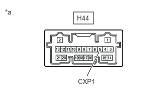
- CHECK MAIN BODY ECU (MULTIPLEX NETWORK BODY ECU)
*a Component without harness connected
(Main Body ECU (Multiplex Network Body ECU)- Check for voltage and pulses according to the value(s) in the table below.
Standard Voltage
Tester Connection Condition Specified Condition H44-5 (CXP1) - Body ground Ignition switch ON Pulse generation Less than approximately 100 seconds after ignition switch turned off Approximately 100 seconds or more after ignition switch turned off 11 to 14 V Result
Proceed to OK NG
Result:
NG
REPLACE MAIN BODY ECU (MULTIPLEX NETWORK BODY ECU). Refer to REMOVAL [12/2019 - 10/2022] , or refer to REMOVAL [10/2022 - 11/2023]
Result:
OK
See step 3
- Check for voltage and pulses according to the value(s) in the table below.
- PERFORM ACTIVE TEST USING GTS
- Perform the Active Test according to the display on the GTS.
Body Electrical > Main Body > Active Test
Tester Display Measurement Item Control Range Diagnostic Note Wiper Power Relay Function to operate the IG1 WIP relay OFF or ON - Body Electrical > Main Body > Active Test
Tester Display Wiper Power Relay OK
IG1 WIP relay operates normally.
Result
Proceed to OK NG
Result:
NG
See step 9
Result:
OK
See step 4
- Perform the Active Test according to the display on the GTS.
- CHECK HARNESS AND CONNECTOR (WINDSHIELD WIPER RELAY ASSEMBLY - BODY GROUND)
- Disconnect the A6 windshield wiper relay assembly connector.
- Measure the resistance according to the value(s) in the table below.
Standard Resistance
Tester Connection Condition Specified Condition A6-3 (E) - Body ground Always Below 1 Ω A7-5 (ES) - Body ground Always Below 1 Ω Result
Proceed to OK NG
Result:
NG
REPAIR OR REPLACE HARNESS OR CONNECTOR
Result:
OK
See step 5
- CHECK HARNESS AND CONNECTOR (POWER SOURCE - WINDSHIELD WIPER RELAY ASSEMBLY)
- Measure the voltage according to the value(s) in the table below.
Standard Voltage
Tester Connection Condition Specified Condition A6-8 (+B) - Body ground Ignition switch ON 11 to 14 V Less than approximately 60 seconds after ignition switch turned off 11 to 14 V Approximately 60 seconds or more after ignition switch turned off Below 1 V Result
Proceed to OK NG
Result:
OK
REPLACE WINDSHIELD WIPER RELAY ASSEMBLY. Refer to REMOVAL [12/2019 - 10/2022] , or refer to REMOVAL [10/2022 - 11/2023]
Result:
NG
See step 6
- Measure the voltage according to the value(s) in the table below.
- INSPECT WIPER RELAY
- Inspect the WIPER relay.
Refer to ON-VEHICLE INSPECTION [12/2019 - ]
Result
Proceed to OK NG
Result:
NG
REPLACE WIPER RELAY
Result:
OK
See step 7
- Inspect the WIPER relay.
- CHECK HARNESS AND CONNECTOR (POWER SOURCE - WIPER RELAY)
- Measure the voltage according to the value(s) in the table below.
Standard Voltage
Tester Connection Condition Specified Condition 5 (WIPER relay) - Body ground Ignition switch off*1
Always*211 to 14 V - *1: for HV Model
- *2: for Gasoline Model
Result
Proceed to OK NG
Result:
NG
REPAIR OR REPLACE HARNESS OR CONNECTOR
Result:
OK
See step 8
- Measure the voltage according to the value(s) in the table below.
- CHECK HARNESS AND CONNECTOR (WINDSHIELD WIPER RELAY ASSEMBLY - WIPER RELAY)
- Measure the resistance according to the value(s) in the table below.
Standard Resistance
Tester Connection Condition Specified Condition A6-8 (+B) - 3 (WIPER relay) Always Below 1 Ω A6-8 (+B) or 3 (WIPER relay) - Body ground Always 10 kΩ or higher Result
Proceed to OK NG
Result:
OK
REPLACE MAIN BODY ECU (MULTIPLEX NETWORK BODY ECU). Refer to REMOVAL [12/2019 - 10/2022] , or refer to REMOVAL [10/2022 - 11/2023]
Result:
NG
REPAIR OR REPLACE HARNESS OR CONNECTOR
- Measure the resistance according to the value(s) in the table below.
- INSPECT WIPER RELAY
- Inspect the WIPER relay.
Refer to ON-VEHICLE INSPECTION [12/2019 - ]
Result
Proceed to OK NG
Result:
NG
REPLACE WIPER RELAY
Result:
OK
See step 10
- Inspect the WIPER relay.
- CHECK HARNESS AND CONNECTOR (WIPER RELAY - MAIN BODY ECU (MULTIPLEX NETWORK BODY ECU))
- Disconnect the H43 main body ECU (multiplex network body ECU) connector.
- Measure the resistance according to the value(s) in the table below.
Standard Resistance
Tester Connection Condition Specified Condition 2 (WIPER relay) - H43-21 (WPS) Always Below 1 Ω 2 (WIPER relay) or H43-21 (WPS) - Body ground Always 10 kΩ or higher Result
Proceed to OK NG
Result:
NG
REPAIR OR REPLACE HARNESS OR CONNECTOR
Result:
OK
See step 11
- CHECK HARNESS AND CONNECTOR (WIPER RELAY - BODY GROUND)
- Measure the resistance according to the value(s) in the table below.
Standard Resistance
Tester Connection Condition Specified Condition 1 (WIPER relay) - Body ground Always Below 1 Ω Result
Proceed to OK NG
Result:
OK
REPLACE MAIN BODY ECU (MULTIPLEX NETWORK BODY ECU). Refer to REMOVAL [12/2019 - 10/2022] , or refer to REMOVAL [10/2022 - 11/2023]
Result:
NG
REPAIR OR REPLACE HARNESS OR CONNECTOR
- Measure the resistance according to the value(s) in the table below.