Power Steering ECU Communication Stop Mode [11/2023 - ]: Procedure
- CHECK FOR OPEN IN CAN BUS LINES (RACK AND PINION POWER STEERING GEAR ASSEMBLY MAIN LINE)
- Disconnect the cable from the negative (-) battery terminal.
- Disconnect the C67 rack and pinion power steering gear assembly connector.
- Measure the resistance according to the value(s) in the table below.
Standard Resistance
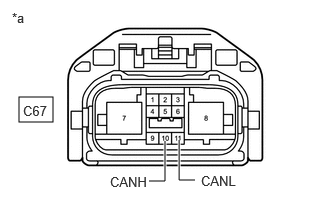
Tester Connection Condition Specified Condition C67-10 (CANH) - C67-11 (CANL) Cable disconnected from negative (-) battery terminal 108 to 132 Ω *a Front view of wire harness connector
(to Rack and Pinion Power Steering Gear Assembly)Result
Proceed to OK NG
Result:
NG
REPAIR OR REPLACE CAN MAIN BUS LINES OR CONNECTOR (RACK AND PINION POWER STEERING GEAR ASSEMBLY)
Result:
OK
See step 2
- CHECK HARNESS AND CONNECTOR (POWER SOURCE CIRCUIT)
- Measure the resistance according to the value(s) in the table below.
Standard Resistance
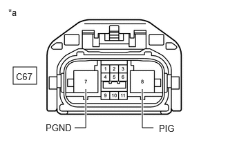
Tester Connection Condition Specified Condition C67-7 (PGND) - Body ground Cable disconnected from negative (-) battery terminal Below 1 Ω *a Front view of wire harness connector
(to Rack and Pinion Power Steering Gear Assembly) - Reconnect the cable to the negative (-) battery terminal.
- Measure the voltage according to the value(s) in the table below.
Standard Voltage
Tester Connection Condition Specified Condition C67-8 (PIG) - Body ground Always 11 to 14 V Result
Proceed to OK NG
Result:
NG
REPAIR OR REPLACE HARNESS OR CONNECTOR (POWER SOURCE CIRCUIT)
Result:
OK
See step 3
- Measure the resistance according to the value(s) in the table below.
- CHECK VEHICLE TYPE
Result:
B
See step 5
Result:
A
See step 4
- CHECK HARNESS AND CONNECTOR (POWER SOURCE CIRCUIT)
- Reconnect the cable to the negative (-) battery terminal.
- Measure the voltage according to the value(s) in the table below.
Standard Voltage
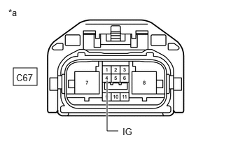
Tester Connection Condition Specified Condition C67-4 (IG) - Body ground Ignition switch ON 10.5 to 16 V *a Front view of wire harness connector
(to Rack and Pinion Power Steering Gear Assembly)Result
Proceed to OK NG
Result:
OK
REPLACE RACK AND PINION POWER STEERING GEAR ASSEMBLY
Refer to REMOVAL [11/2023 - ]
Result:
NG
GO TO STOP AND START SYSTEM (FOR BACKUP BOOST CONVERTER CIRCUIT)
- CHECK HARNESS AND CONNECTOR (POWER SOURCE CIRCUIT)
- Reconnect the cable to the negative (-) battery terminal.
- Measure the voltage according to the value(s) in the table below.
Standard Voltage
Tester Connection Condition Specified Condition C67-4 (IG) - Body ground Ignition switch ON 8 to 16 V *a Front view of wire harness connector
(to Rack and Pinion Power Steering Gear Assembly)Result
Proceed to OK NG
Result:
OK
REPLACE RACK AND PINION POWER STEERING GEAR ASSEMBLY
Refer to REMOVAL [11/2023 - ]
Result:
NG
REPAIR OR REPLACE HARNESS OR CONNECTOR (POWER SOURCE CIRCUIT)