DTC P1603-00: Engine Stall History [12/2019 - 10/2022]: Procedure
- CHECK DTC OUTPUT (SFI SYSTEM)
- Read the DTCs.
Powertrain > Engine > Trouble Codes
Result
Result Proceed to SFI system DTCs are not output A SFI system starting malfunction circuit DTC is output and starter assembly does not operate SFI system starting malfunction circuit DTC is output and starter assembly operates B DTCs other than SFI system starting malfunction circuit DTC are output HINT:
- According to the display on the GTS, check the Freeze Frame Data item [Cranking Time] in the sets of Freeze Frame Data.
- If the value of [Cranking Time] is approximately 3 seconds, the stop and start control system or starter system may be malfunctioning.
- If the value of [Cranking Time] is small (approximately 0.5 seconds or less: the minimum value varies depending on the model), the SFI system may be malfunctioning.
- The Data List item [Cranking Time] indicates the length of time starter operation is requested by the engine stop and start ECU. If the engine speed exceeds the specified value, the engine stop and start ECU cancels its start request.
Result:
B
GO TO SFI SYSTEM. Refer to DIAGNOSTIC TROUBLE CODE CHART [12/2019 - 09/2020] , or refer to DIAGNOSTIC TROUBLE CODE CHART [09/2020 - 10/2021] , or refer to DIAGNOSTIC TROUBLE CODE CHART [10/2021 - 10/2022]
Result:
A
See step 2
- Read the DTCs.
- CHECK FREEZE FRAME DATA NOTE:
The Freeze Frame Data is cleared when DTCs are cleared. Be sure to make a note of necessary data in advance.
HINT:
Using the time-series Freeze Frame Data, confirm the Freeze Frame Data recorded the moment the DTC was stored and after the DTC was stored. This information can be useful when troubleshooting.
- According to the prompts on the GTS screen, read the time-series Freeze Frame Data to confirm the vehicle conditions when an engine stall occurred while stop and start control was operating.
- Check the Freeze Frame Data for engine stall history and engine start failure.
Result
GTS Display Result Proceed to Engine Stall History during Stop&Start (Hood Open) Yes A Engine Stall History during Stop&Start (Collision or Battery Voltage Low) Yes B Engine Stall History during Engine Starting (Collision) Yes Engine Start Fail Yes C
Result:
B
See step 7
Result:
C
See step 8
Result:
A
See step 3
- READ VALUE USING GTS (HOOD COURTESY SWITCH) NOTE:
Before performing this step, check that the engine hood can be opened by pulling the hood lock control cable.
- According to the display on the GTS, read the Data List.
Powertrain > Stop and Start > Data List
Tester Display Hood Courtesy Switch OK
GTS Display Condition Normal Condition Hood Courtesy Switch Engine hood closed ON Engine hood open OFF Result
Proceed to OK NG
Result:
OK
USE SIMULATION METHOD TO CHECK. Refer to HOW TO PROCEED WITH TROUBLESHOOTING [12/2019 - ]
Result:
NG
See step 4
- According to the display on the GTS, read the Data List.
- INSPECT ENGINE HOOD COURTESY SWITCH (HOOD LOCK ASSEMBLY)
Refer to INSPECTION [12/2019 - ]
Result
Proceed to OK NG Result:
NG
REPLACE ENGINE HOOD COURTESY SWITCH (HOOD LOCK ASSEMBLY). Refer to REMOVAL [12/2019 - 09/2020] , or refer to REMOVAL [09/2020 - ]
Result:
OK
See step 5
- CHECK HARNESS AND CONNECTOR (ENGINE HOOD COURTESY SWITCH (HOOD LOCK ASSEMBLY) - BODY GROUND)
- Disconnect the engine hood courtesy switch (hood lock assembly) connector.
- Measure the resistance according to the value(s) in the table below.
Standard Resistance
Tester Connection Condition Specified Condition A21-2 (E) - Body ground Always Below 1 Ω Result
Proceed to OK NG
Result:
NG
REPAIR OR REPLACE HARNESS OR CONNECTOR
Result:
OK
See step 6
- CHECK HARNESS AND CONNECTOR (ENGINE STOP AND START ECU ASSEMBLY - ENGINE HOOD COURTESY SWITCH (HOOD LOCK ASSEMBLY))
- Disconnect the engine stop and start ECU assembly connector.
- Disconnect the engine hood courtesy switch (hood lock assembly) connector.
- Measure the resistance according to the value(s) in the table below.
Standard Resistance
Tester Connection Condition Specified Condition A34-7 (BNT1) - A21-1 (+) Always Below 1 Ω A34-7 (BNT1) or A21-1 (+) - Body ground and other terminals Always 10 kΩ or higher Result
Proceed to OK NG
Result:
OK
REPLACE ENGINE STOP AND START ECU. Refer to REMOVAL [12/2019 - 10/2022]
Result:
NG
REPAIR OR REPLACE HARNESS OR CONNECTOR
- CHECK VEHICLE CONDITION (COLLISION HISTORY)
- Check if the vehicle was in a collision when the engine stalled.
Result
Result Proceed to Vehicle was in collision when engine stalled A Vehicle was not in collision when engine stalled B HINT:
When "Engine Stall History during Stop&Start (Collision or Battery Voltage Low)" or "Engine Stall History during Engine Starting (Collision)" is stored:
This may have been stored because the vehicle was in a collision or a collision detection signal was input while stop and start control was operating.
Result:
A
END (ENGINE STALLED BECAUSE COLLISION DETECTION SIGNAL WAS RECEIVED)
Result:
B
GO TO AIRBAG SYSTEM. Refer to HOW TO PROCEED WITH TROUBLESHOOTING [12/2019 - 11/2023]
- Check if the vehicle was in a collision when the engine stalled.
- CHECK HARNESS AND CONNECTOR (ENGINE STOP AND START ECU - ST RELAY)
- Disconnect the engine stop and start ECU connector.
- Remove the ST relay from the No. 1 engine room relay block and No. 1 junction block assembly.
- Disconnect the certification ECU (smart key ECU assembly) connector.
- Disconnect the park/neutral position switch assembly connector.
- Disconnect the ECM connector.
- Measure the resistance according to the value(s) in the table below.
Standard Resistance
Tester Connection Condition Specified Condition A34-21 (STA) - 2 (ST relay) Always Below 1 Ω A34-21 (STA) or 2 (ST relay) - Body ground and other terminals Always 10 kΩ or higher Result
Proceed to OK NG
Result:
NG
REPAIR OR REPLACE HARNESS OR CONNECTOR (ENGINE STOP AND START ECU - ST RELAY)
Result:
OK
See step 9
- CHECK HARNESS AND CONNECTOR (ST RELAY - BODY GROUND)
- Remove the ST relay from the No. 1 engine room relay block and No. 1 junction block assembly.
- Measure the resistance according to the value(s) in the table below.
Standard Resistance
Tester Connection Condition Specified Condition 1 (ST relay) - Body ground Always Below 1 Ω Result
Proceed to OK NG
Result:
NG
REPAIR OR REPLACE HARNESS OR CONNECTOR (ST RELAY - BODY GROUND)
Result:
OK
See step 10
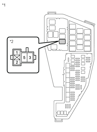
- CHECK HARNESS AND CONNECTOR (ST RELAY - BATTERY)
*1 No. 1 Engine Room Relay Block and No. 1 Junction Block Assembly *2 ST Relay - Remove the ST relay from the No. 1 engine room relay block and No. 1 junction block assembly.
- Measure the voltage according to the value(s) in the table below.
Standard Voltage
Tester Connection Condition Specified Condition 5 (ST relay) - Body ground Always 9.5 to 14 V Result
Proceed to OK NG
Result:
NG
REPAIR OR REPLACE HARNESS OR CONNECTOR (ST RELAY - BATTERY)
Result:
OK
See step 11
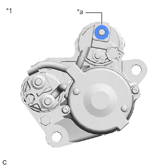
- CHECK HARNESS AND CONNECTOR (STARTER ASSEMBLY - BATTERY)
*1 Starter Assembly *a C69-1 (B) - Measure the voltage according to the value(s) in the table below.
Standard Voltage
Tester Connection Condition Specified Condition C69-1 (B) - Body ground Always 9.5 to 14 V NOTE:Before performing this step, check that the starter assembly connector C69 is not disconnected or loose.
Result
Proceed to OK NG
Result:
NG
REPAIR OR REPLACE HARNESS OR CONNECTOR
Result:
OK
See step 12
- Measure the voltage according to the value(s) in the table below.
- CHECK HARNESS AND CONNECTOR (ST RELAY - STARTER ASSEMBLY)
- Remove the ST relay from the no. 1 engine room relay block and no. 1 junction block assembly.
- Disconnect the starter assembly connector.
- Measure the resistance according to the value(s) in the table below.
Standard Resistance
Tester Connection Condition Specified Condition 3 (ST relay) - C56-1 (ST) Always Below 1 Ω 3 (ST relay) - C58-1 (ZYV) Always Below 1 Ω Result
Proceed to OK NG
Result:
NG
REPAIR OR REPLACE HARNESS OR CONNECTOR (ST RELAY - STARTER ASSEMBLY)
Result:
OK
See step 13
- INSPECT RELAY (ST RELAY)
Refer to PROCEDURE - Step 1
Result
Proceed to OK NG Result:
NG
REPLACE RELAY (ST RELAY)
Result:
OK
See step 14
- INSPECT STARTER ASSEMBLY
Refer to INSPECTION [12/2019 - 10/2022]
Result
Proceed to OK NG Result:
OK
REPLACE ENGINE STOP AND START ECU. Refer to REMOVAL [12/2019 - 10/2022]
Result:
NG
REPLACE STARTER ASSEMBLY. Refer to REMOVAL [12/2019 - 09/2020] , or refer to REMOVAL [09/2020 - 10/2022]