Main Body ECU Communication Stop Mode [12/2019 - 11/2023]: Procedure
- CHECK FOR OPEN IN CAN BUS LINES (MAIN BODY ECU (MULTIPLEX NETWORK BODY ECU) BRANCH LINE)
- Disconnect the cable from the negative (-) battery terminal.
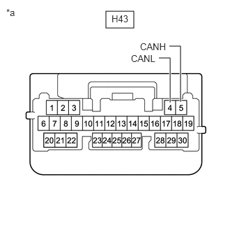
- Disconnect the H43 main body ECU (multiplex network body ECU) connector.
- Measure the resistance according to the value(s) in the table below.
Standard Resistance
Tester Connection Condition Specified Condition H43-5 (CANH) - H43-4 (CANL) Cable disconnected from negative (-) battery terminal 54 to 69 Ω *a Front view of wire harness connector
(to Main Body ECU (Multiplex Network Body ECU))Result
Result OK NG
Result:
NG
REPAIR OR REPLACE CAN BRANCH LINES OR CONNECTOR (MAIN BODY ECU (MULTIPLEX NETWORK BODY ECU))
Result:
OK
See step 2
- CHECK HARNESS AND CONNECTOR (GROUND CIRCUIT)
- Remove the main body ECU (multiplex network body ECU).
Refer to REMOVAL [12/2019 - 10/2022] , or refer to REMOVAL [10/2022 - 11/2023]
- Measure the resistance according to the value(s) in the table below.
Standard Resistance
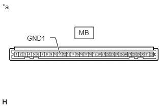
Tester Connection Condition Specified Condition MB-11 (GND1) - Body ground Cable disconnected from negative (-) battery terminal Below 1 Ω *a Front view of wire harness connector
(to Main Body ECU (Multiplex Network Body ECU))NOTE:Perform this inspection with the wire harness connected to the instrument panel junction block assembly.
Result
Result OK NG
Result:
NG
See step 7
Result:
OK
See step 3
- Remove the main body ECU (multiplex network body ECU).
- CHECK HARNESS AND CONNECTOR (BECU SIGNAL CIRCUIT)
- Reconnect the cable to the negative (-) battery terminal.
- Measure the voltage according to the value(s) in the table below.
Standard Voltage
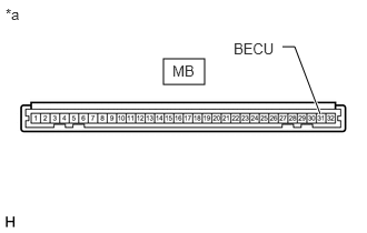
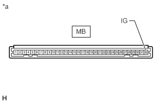
Tester Connection Condition Specified Condition MB-31 (BECU) - Body ground Always 11 to 14 V NOTE:Perform this inspection with the wire harness connected to the instrument panel junction block assembly.
*a Front view of wire harness connector
(to Main Body ECU (Multiplex Network Body ECU))Result
Result OK NG
Result:
NG
See step 6
Result:
OK
See step 4
- CHECK HARNESS AND CONNECTOR (ACC SIGNAL CIRCUIT)
- Measure the voltage according to the value(s) in the table below.
Standard Voltage
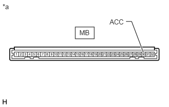
Tester Connection Condition Specified Condition MB-30 (ACC) - Body ground Ignition switch ON 11 to 14 V NOTE:Perform this inspection with the wire harness connected to the instrument panel junction block assembly.
*a Front view of wire harness connector
(to Main Body ECU (Multiplex Network Body ECU))Result
Result OK NG
Result:
NG
GO TO LIGHTING (INT) SYSTEM (ACC SIGNAL CIRCUIT)
Refer to ACC Signal Circuit [12/2019 - 11/2023]
Result:
OK
See step 5
- Measure the voltage according to the value(s) in the table below.
- CHECK HARNESS AND CONNECTOR (IG SIGNAL CIRCUIT)
- Measure the voltage according to the value(s) in the table below.
Standard Voltage
Tester Connection Condition Specified Condition MB-32 (IG) - Body ground Ignition switch ON 11 to 14 V NOTE:Perform this inspection with the wire harness connected to the instrument panel junction block assembly.
*a Front view of wire harness connector
(to Main Body ECU (Multiplex Network Body ECU))Result
Result OK NG
Result:
OK
REPLACE MAIN BODY ECU (MULTIPLEX NETWORK BODY ECU)
Refer to REMOVAL [12/2019 - 10/2022] , or refer to REMOVAL [10/2022 - 11/2023]
Result:
NG
GO TO LIGHTING (INT) SYSTEM (IG SIGNAL CIRCUIT)
- Measure the voltage according to the value(s) in the table below.
- CHECK HARNESS AND CONNECTOR (BECU SIGNAL CIRCUIT)
- Disconnect the cable from the negative (-) battery terminal.
- Disconnect the 4C instrument panel junction block assembly connector.
- Reconnect the cable to the negative (-) battery terminal.
- Measure the voltage according to the value(s) in the table below.
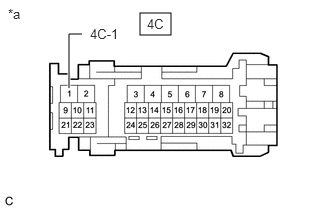
*a Front view of wire harness connector
(to Instrument Panel Junction Block Assembly)Standard Voltage
Tester Connection Condition Specified Condition 4C-1 - Body ground Always 11 to 14 V Result
Result OK NG
Result:
OK
REPLACE INSTRUMENT PANEL JUNCTION BLOCK ASSEMBLY
Refer to REMOVAL [12/2019 - 10/2022] , or refer to REMOVAL [10/2022 - 11/2023]
Result:
NG
REPAIR OR REPLACE HARNESS OR CONNECTOR (BECU SIGNAL CIRCUIT)
- CHECK HARNESS AND CONNECTOR (GROUND CIRCUIT)
- Disconnect the cable from the negative (-) battery terminal.
- Disconnect the 4B instrument panel junction block assembly connector.
- Measure the resistance according to the value(s) in the table below.
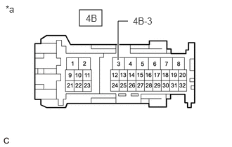
*a Front view of wire harness connector
(to Instrument Panel Junction Block Assembly)Standard Resistance
Tester Connection Condition Specified Condition 4B-3 - Body ground Cable disconnected from negative (-) battery terminal Below 1 Ω Result
Result OK NG
Result:
OK
REPLACE INSTRUMENT PANEL JUNCTION BLOCK ASSEMBLY
Refer to REMOVAL [12/2019 - 10/2022] , or refer to REMOVAL [10/2022 - 11/2023]
Result:
NG
REPAIR OR REPLACE HARNESS OR CONNECTOR (GROUND CIRCUIT)