DTC P2796-14: Electromagnetic Oil Pump Circuit Open [10/2022 - ]: Procedure
- CHECK VEHICLE CONTROL HISTORY
- Enter the following menus: Powertrain / Stop and Start / Utility / Vehicle Control History (RoB).
Powertrain > Stop and Start > Utility
Tester Display Vehicle Control History (RoB) - Check vehicle control history.
Result
Result Proceed to Vehicle control history item BBC Boosting Output Overcurrent stored A Vehicle control history item not stored B
Result:
B
See step 9
Result:
A
See step 2
- Enter the following menus: Powertrain / Stop and Start / Utility / Vehicle Control History (RoB).
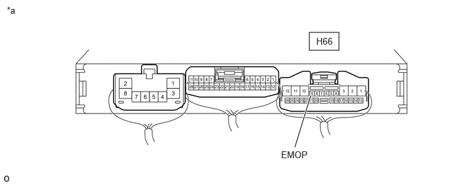
- CHECK HARNESS AND CONNECTOR (ENGINE STOP AND START ECU - BODY GROUND)
*a Component with harness connected
(Engine Stop and Start ECU)- - - Measure the resistance according to the value(s) in the table below.
Standard Resistance
Tester Connection Condition Specified Condition H66-9 (EMOP) - Body ground Always 10 kΩ or higher Result
Proceed to OK NG
Result:
NG
See step 7
Result:
OK
See step 3
- Measure the resistance according to the value(s) in the table below.
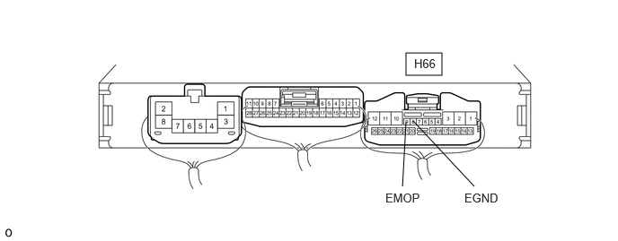
- CHECK HARNESS AND CONNECTOR (ENGINE STOP AND START ECU - TRANSMISSION WIRE)
- Disconnect the engine stop and start ECU connector.
- Measure the resistance according to the value(s) in the table below.
Standard Resistance
Tester Connection Condition Specified Condition H66-9 (EMOP) - H66-8 (EGND) 20°C (68°F) 5.0 to 5.6 Ω Result
Proceed to OK NG
Result:
NG
See step 5
Result:
OK
See step 4
- CHECK ENGINE STOP AND START ECU
*a Component without harness connected
(Engine Stop and Start ECU)- - - Disconnect the engine stop and start ECU connector.
- Measure the resistance according to the value(s) in the table below.
Standard Resistance
Tester Connection Condition Specified Condition H66-9 (EMOP) - H66-8 (EGND) Always 10 kΩ or higher Result
Proceed to OK NG
Result:
OK
GO TO BACKUP BOOST CONVERTER CIRCUIT. Refer to Backup Boost Converter Circuit [10/2022 - 11/2023] , or refer to Backup Boost Converter Circuit [11/2023 - ]
Result:
NG
REPLACE ENGINE STOP AND START ECU. Refer to REMOVAL [10/2022 - 11/2023] , or refer to REMOVAL [11/2023 - ]
- CHECK HARNESS AND CONNECTOR (ENGINE STOP AND START ECU - TRANSMISSION WIRE)
- Disconnect the engine stop and start ECU connector.
- Disconnect the transmission wire connector.
- Measure the resistance according to the value(s) in the table below.
Standard Resistance
Tester Connection Condition Specified Condition H66-8 (EGND) - C51-28 (EMP-) Always Below 1 Ω H66-9 (EMOP) - C51-29 (EMP+) Always Below 1 Ω Result
Proceed to OK NG
Result:
NG
REPAIR OR REPLACE HARNESS OR CONNECTOR
Result:
OK
See step 6
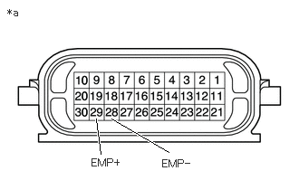
- INSPECT TRANSMISSION WIRE (OIL PUMP WITH SOLENOID ASSEMBLY)
- Disconnect the transmission wire connector.
- Measure the resistance according to the value(s) in the table below.
*a Component without harness connected
(Transmission Wire)Standard Resistance
Tester Connection Condition Specified Condition 29 (EMP+) - 28 (EMP-) 20°C (68°F) 5.0 to 5.6 Ω Result
Proceed to OK NG
Result:
OK
REPLACE OIL PUMP WITH SOLENOID ASSEMBLY. Refer to PROCEDURE - Step 4
Result:
NG
REPLACE TRANSMISSION WIRE. Refer to REMOVAL [10/2022 - ]
- CHECK HARNESS AND CONNECTOR (ENGINE STOP AND START ECU - BODY GROUND)
*a Component with harness connected
(Engine Stop and Start ECU)- - - Disconnect the transmission wire connector.
- Measure the resistance according to the value(s) in the table below.
Standard Resistance
Tester Connection Condition Specified Condition H66-9 (EMOP) - Body ground Always 10 kΩ or higher Result
Proceed to OK NG
Result:
OK
REPLACE TRANSMISSION WIRE. Refer to REMOVAL [10/2022 - ]
Result:
NG
See step 8
- CHECK HARNESS AND CONNECTOR (ENGINE STOP AND START ECU - TRANSMISSION WIRE)
- Disconnect the engine stop and start ECU connector.
- Disconnect the transmission wire connector.
- Measure the resistance according to the value(s) in the table below.
Standard Resistance
Tester Connection Condition Specified Condition H66-9 (EMOP) or C51-29 (EMP+) - Body ground Always 10 kΩ or higher Result
Proceed to OK NG
Result:
OK
REPLACE ENGINE STOP AND START ECU. Refer to REMOVAL [10/2022 - 11/2023] , or refer to REMOVAL [11/2023 - ]
Result:
NG
REPAIR OR REPLACE HARNESS OR CONNECTOR
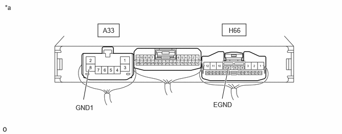
- CHECK ENGINE STOP AND START ECU (EGND TERMINAL WAVEFORM)
- Turn the ignition switch to ON.
HINT:
Do not start the engine.
- Turn the GTS on.
- Connect an oscilloscope to the EGND and GND1 terminals of the engine stop and start ECU connectors.
*a Component with harness connected
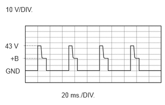
(Engine Stop and Start ECU)- - - Check the waveform while performing the Active Test.
Powertrain > Stop and Start > Active Test
Tester Display Electromagnetic Oil Pump Item Condition Tester Connection H66-8 (EGND) - A33-8 (GND1) Tool Setting 10 V/DIV., 20 ms./DIV. Condition - Ignition switch ON (engine is stopped)
- Active Test "Electromagnetic Oil Pump" being performed
Standard
The waveform is similar to that shown in the illustration.
Result
Result Proceed to Constant value below 1 V A Constant value between 10 to 14 V B Waveform output as in illustration C
Result:
B
REPLACE ENGINE STOP AND START ECU. Refer to REMOVAL [10/2022 - 11/2023] , or refer to REMOVAL [11/2023 - ]
Result:
C
USE SIMULATION METHOD TO CHECK. Refer to HOW TO PROCEED WITH TROUBLESHOOTING [12/2019 - ]
Result:
A
See step 10
- Turn the ignition switch to ON.
- CHECK HARNESS AND CONNECTOR (ENGINE STOP AND START ECU - BODY GROUND)
*a Component with harness connected
(Engine Stop and Start ECU)- - - Measure the resistance according to the value(s) in the table below.
Standard Resistance
Tester Connection Condition Specified Condition H66-8 (EGND) - Body ground Ignition switch off 10 kΩ or higher Result
Proceed to OK NG
Result:
NG
See step 14
Result:
OK
See step 11
- Measure the resistance according to the value(s) in the table below.
- CHECK TERMINAL VOLTAGE (EMP+ TERMINAL)
- Disconnect the transmission wire connector.
- Turn the ignition switch to ON.
HINT:
Do not start the engine.
- Measure the voltage according to the value(s) in the table below.
Powertrain > Stop and Start > Active Test
Tester Display Electromagnetic Oil Pump Standard Voltage
Tester Connection Condition Specified Condition C51-29 (EMP+) - Body ground - Ignition switch ON (engine is stopped)
- Active Test "Electromagnetic Oil Pump" being performed
10 to 14 V Result
Proceed to OK NG
Result:
NG
See step 13
Result:
OK
See step 12
- INSPECT TRANSMISSION WIRE (OIL PUMP WITH SOLENOID ASSEMBLY)
- Disconnect the transmission wire connector.
*a Component without harness connected
(Transmission Wire) - Measure the resistance according to the value(s) in the table below.
Standard Resistance
Tester Connection Condition Specified Condition 29 (EMP+) - 28 (EMP-) 20°C (68°F) 5.0 to 5.6 Ω Result
Proceed to OK NG
Result:
OK
REPAIR OR REPLACE HARNESS OR CONNECTOR (ENGINE STOP AND START ECU - TRANSMISSION WIRE)
Result:
NG
See step 6
- Disconnect the transmission wire connector.
- CHECK TERMINAL VOLTAGE (EMOP TERMINAL)
*a Component with harness connected
(Engine Stop and Start ECU)- - - Disconnect the transmission wire connector.
- Turn the ignition switch to ON.
HINT:
Do not start the engine.
- Measure the voltage according to the value(s) in the table below.
Powertrain > Stop and Start > Active Test
Tester Display Electromagnetic Oil Pump Standard Voltage
Tester Connection Condition Specified Condition H66-9 (EMOP) - Body ground - Ignition switch ON (engine is stopped)
- Active Test "Electromagnetic Oil Pump" being performed
10 to 14 V Result
Proceed to OK NG
Result:
OK
REPAIR OR REPLACE HARNESS OR CONNECTOR (ENGINE STOP AND START ECU - TRANSMISSION WIRE)
Result:
NG
REPLACE ENGINE STOP AND START ECU. Refer to REMOVAL [10/2022 - 11/2023] , or refer to REMOVAL [11/2023 - ]
- CHECK HARNESS AND CONNECTOR (ENGINE STOP AND START ECU - BODY GROUND)
- Disconnect the engine stop and start ECU connector.
- Measure the resistance according to the value(s) in the table below.
Standard Resistance
Tester Connection Condition Specified Condition H66-8 (EGND) - Body ground Always 10 kΩ or higher Result
Proceed to OK NG
Result:
OK
REPLACE ENGINE STOP AND START ECU. Refer to REMOVAL [10/2022 - 11/2023] , or refer to REMOVAL [11/2023 - ]
Result:
NG
See step 15
- CHECK HARNESS AND CONNECTOR (ENGINE STOP AND START ECU - TRANSMISSION WIRE)
- Disconnect the engine stop and start ECU connector.
- Disconnect the transmission wire connector.
- Measure the resistance according to the value(s) in the table below.
Standard Resistance
Tester Connection Condition Result H66-8 (EGND) or C51-28 (EMP-) - Body ground Always 10 kΩ or higher Result
Proceed to OK NG
Result:
OK
REPLACE TRANSMISSION WIRE. Refer to REMOVAL [10/2022 - ]
Result:
NG
REPAIR OR REPLACE HARNESS OR CONNECTOR