Combination Meter ECU Communication Stop Mode [10/2022 - 11/2023]: Procedure
- CHECK VEHICLE TYPE
Result:
B
See step 7
Result:
A
See step 2
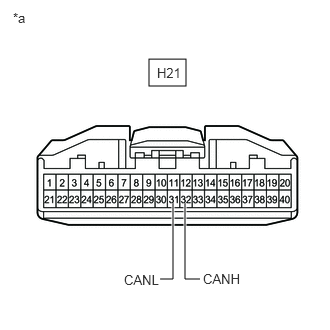
- CHECK FOR OPEN IN CAN BUS LINES (COMBINATION METER ASSEMBLY MAIN LINE)
- Disconnect the cable from the negative (-) battery terminal.
- Disconnect the H21 combination meter assembly connector.
- Measure the resistance according to the value(s) in the table below.
Standard Resistance
Tester Connection Condition Specified Condition H21-32 (CANH) - H21-31 (CANL) Cable disconnected from negative (-) battery terminal 108 to 132 Ω *a Front view of wire harness connector
(to Combination Meter Assembly)Result
Result OK NG
Result:
NG
REPAIR OR REPLACE CAN MAIN BUS LINES OR CONNECTOR (COMBINATION METER ASSEMBLY)
Result:
OK
See step 3
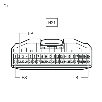
- CHECK HARNESS AND CONNECTOR (POWER SOURCE CIRCUIT)
- Measure the resistance according to the value(s) in the table below.
Standard Resistance
Tester Connection Condition Specified Condition H21-2 (EP) - Body ground Cable disconnected from negative (-) battery terminal Below 1 Ω H21-21 (ES) - Body ground Cable disconnected from negative (-) battery terminal Below 1 Ω *a Front view of wire harness connector
(to Combination Meter Assembly) - Reconnect the cable to the negative (-) battery terminal.
- Measure the voltage according to the value(s) in the table below.
Standard Voltage
Tester Connection Condition Specified Condition H21-40 (B) - Body ground Always 11 to 14 V Result
Result OK NG
Result:
NG
REPAIR OR REPLACE HARNESS OR CONNECTOR (POWER SOURCE CIRCUIT)
Result:
OK
See step 4
- Measure the resistance according to the value(s) in the table below.
- CHECK VEHICLE TYPE
Result:
B
See step 6
Result:
A
See step 5
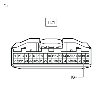
- CHECK HARNESS AND CONNECTOR (POWER SOURCE CIRCUIT)
- Measure the voltage according to the value(s) in the table below.
Standard Voltage
Tester Connection Condition Specified Condition H21-39 (IG+) - Body ground Ignition switch ON 10.5 to 16 V *a Front view of wire harness connector
(to Combination Meter Assembly)Result
Result OK NG
Result:
OK
REPLACE COMBINATION METER ASSEMBLY
Refer to REMOVAL [12/2019 - ]
Result:
NG
GO TO STOP AND START SYSTEM (FOR BACKUP BOOST CONVERTER CIRCUIT)
- Measure the voltage according to the value(s) in the table below.
- CHECK HARNESS AND CONNECTOR (POWER SOURCE CIRCUIT)
- Measure the voltage according to the value(s) in the table below.
Standard Voltage
Tester Connection Condition Specified Condition H21-39 (IG+) - Body ground Ignition switch ON 11 to 14 V *a Front view of wire harness connector
(to Combination Meter Assembly)Result
Result OK NG
Result:
OK
REPLACE COMBINATION METER ASSEMBLY
Refer to REMOVAL [12/2019 - ]
Result:
NG
REPAIR OR REPLACE HARNESS OR CONNECTOR (POWER SOURCE CIRCUIT)
- Measure the voltage according to the value(s) in the table below.
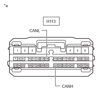
- CHECK FOR OPEN IN CAN BUS LINES (COMBINATION METER ASSEMBLY MAIN LINE)
- Disconnect the cable from the negative (-) battery terminal.
- Disconnect the H113 combination meter assembly connector.
- Measure the resistance according to the value(s) in the table below.
Standard Resistance
Tester Connection Condition Specified Condition H113-31 (CANH) - H113-14 (CANL) Cable disconnected from negative (-) battery terminal 108 to 132 Ω *a Front view of wire harness connector
(to Combination Meter Assembly)Result
Result OK NG
Result:
NG
REPAIR OR REPLACE HARNESS OR CONNECTOR (POWER SOURCE CIRCUIT)
Result:
OK
See step 8
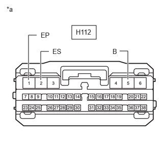
- CHECK HARNESS AND CONNECTOR (POWER SOURCE CIRCUIT)
- Disconnect the H112 combination meter assembly connector.
- Measure the resistance according to the value(s) in the table below.
Standard Resistance
Tester Connection Condition Specified Condition H112-1 (EP) - Body ground Cable disconnected from negative (-) battery terminal Below 1 Ω H112-2 (ES) - Body ground Cable disconnected from negative (-) battery terminal Below 1 Ω *a Front view of wire harness connector
(to Combination Meter Assembly) - Reconnect the cable to the negative (-) battery terminal.
- Measure the voltage according to the value(s) in the table below.
Standard Voltage
Tester Connection Condition Specified Condition H112-5 (B) - Body ground Always 11 to 14 V Result
Result OK NG
Result:
NG
REPAIR OR REPLACE HARNESS OR CONNECTOR (POWER SOURCE CIRCUIT)
Result:
OK
See step 9
- CHECK VEHICLE TYPE
Result:
B
See step 11
Result:
A
See step 10
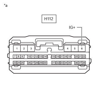
- CHECK HARNESS AND CONNECTOR (POWER SOURCE CIRCUIT)
- Measure the voltage according to the value(s) in the table below.
Standard Voltage
Tester Connection Condition Specified Condition H112-6 (IG+) - Body ground Ignition switch ON 10.5 to 16 V *a Front view of wire harness connector
(to Combination Meter Assembly)Result
Result OK NG
Result:
OK
REPLACE COMBINATION METER ASSEMBLY
Refer to REMOVAL [12/2019 - ]
Result:
NG
GO TO STOP AND START SYSTEM (FOR BACKUP BOOST CONVERTER CIRCUIT)
- Measure the voltage according to the value(s) in the table below.
- CHECK HARNESS AND CONNECTOR (POWER SOURCE CIRCUIT)
- Measure the voltage according to the value(s) in the table below.
Standard Voltage
Tester Connection Condition Specified Condition H112-6 (IG+) - Body ground Ignition switch ON 11 to 14 V *a Front view of wire harness connector
(to Combination Meter Assembly)Result
Result OK NG
Result:
OK
REPLACE COMBINATION METER ASSEMBLY
Refer to REMOVAL [12/2019 - ]
Result:
NG
REPAIR OR REPLACE HARNESS OR CONNECTOR (POWER SOURCE CIRCUIT)
- Measure the voltage according to the value(s) in the table below.