Interior Light Auto Cut Circuit [12/2019 - 11/2023]: Procedure
- PERFORM ACTIVE TEST USING GTS
- Perform the Active Test according to the display on the GTS.
Body Electrical > Main Body > Active Test
Tester Display Measurement Item Control Range Diagnostic Note Relay for Interior Light Auto Cut Function DOME CUT relay OFF or ON When performing this Active Test, turn all the interior lights on. - OFF: DOME CUT relay on (interior lights turn on)
- ON: DOME CUT relay off (interior lights turn off)
Body Electrical > Main Body > Active Test
Tester Display Relay for Interior Light Auto Cut Function OK
All of the interior lights turn off when ON is selected.
Result
Proceed to OK NG
Result:
OK
PROCEED TO NEXT SUSPECTED AREA SHOWN IN PROBLEM SYMPTOMS TABLE. Refer to PROBLEM SYMPTOMS TABLE [12/2019 - 11/2023]
Result:
NG
See step 2
- Perform the Active Test according to the display on the GTS.
- CHECK HARNESS AND CONNECTOR (POWER SOURCE - INSTRUMENT PANEL JUNCTION BLOCK ASSEMBLY)
- Disconnect the 4F instrument panel junction block assembly connector.
- Measure the voltage according to the value(s) in the table below.
Standard Voltage
Tester Connection Condition Specified Condition 4F-1 - Body ground Always*1
Ignition switch off*211 to 14 V *1: for Gasoline Model
*2: for HV Model
Result
Proceed to OK NG
Result:
NG
REPAIR OR REPLACE HARNESS OR CONNECTOR
Result:
OK
See step 3
- INSPECT INSTRUMENT PANEL JUNCTION BLOCK ASSEMBLY
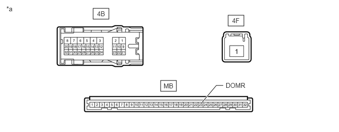
*a Component without harness connected
(Instrument Panel Junction Block Assembly)- - - Remove the main body ECU (multiplex network body ECU) from the instrument panel junction block assembly.
Refer to REMOVAL [12/2019 - 10/2022] , or refer to REMOVAL [10/2022 - 11/2023]
- Measure the voltage according to the value(s) in the table below.
Standard Voltage
Tester Connection Condition Specified Condition 4B-9 - Auxiliary battery negative (-) Auxiliary battery positive (+) → 4F-1
Auxiliary battery negative (-) → MB-23 (DOMR)11 to 14 V 4B-10 - Auxiliary battery negative (-) Auxiliary battery positive (+) → 4F-1
Auxiliary battery negative (-) → MB-23 (DOMR)11 to 14 V - Measure the resistance according to the value(s) in the table below.
Standard Resistance
Tester Connection Condition Specified Condition 4F-1 - 4B-9 Always 10 kΩ or higher 4F-1 - 4B-10 Always 10 kΩ or higher Result
Proceed to OK NG
Result:
OK
REPLACE MAIN BODY ECU (MULTIPLEX NETWORK BODY ECU). Refer to REMOVAL [12/2019 - 10/2022] , or refer to REMOVAL [10/2022 - 11/2023]
Result:
NG
REPLACE INSTRUMENT PANEL JUNCTION BLOCK ASSEMBLY. Refer to REMOVAL [12/2019 - 10/2022] , or refer to REMOVAL [10/2022 - 11/2023]
- Remove the main body ECU (multiplex network body ECU) from the instrument panel junction block assembly.