Door Unlock Detection Switch Circuit [12/2019 - 11/2023]: Procedure
- READ VALUE USING GTS
- Read the Data List according to the display on the GTS.
Body Electrical > Main Body > Data List
Tester Display Measurement Item Range Normal Condition Diagnostic Note FR Door Lock Pos Front door RH unlock detection switch signal LOCK or UNLOCK LOCK: Front door RH locked
UNLOCK: Front door RH unlocked- FL Door Lock Pos Front door LH unlock detection switch signal LOCK or UNLOCK LOCK: Front door LH locked
UNLOCK: Front door LH unlocked- RR-Door Lock Pos SW Rear door RH unlock detection switch signal OFF or ON OFF: Rear door RH locked
ON: Rear door RH unlocked- RL-Door Lock Pos SW Rear door LH unlock detection switch signal OFF or ON OFF: Rear door LH locked
ON: Rear door LH unlocked- Body Electrical > Main Body > Data List
Tester Display FR Door Lock Pos FL Door Lock Pos RR-Door Lock Pos SW RL-Door Lock Pos SW OK
Normal conditions listed above are displayed.
Result
Result Proceed to OK A NG ("FL Door Lock Pos" is not normal) B NG ("FR Door Lock Pos" is not normal) C NG ("RL-Door Lock Pos SW" is not normal) D NG ("RR-Door Lock Pos SW" is not normal) E
Result:
A
PROCEED TO NEXT SUSPECTED AREA SHOWN IN PROBLEM SYMPTOMS TABLE. Refer to PROBLEM SYMPTOMS TABLE [12/2019 - 11/2023]
Result:
C
See step 5
Result:
D
See step 8
Result:
E
See step 11
Result:
B
See step 2
- Read the Data List according to the display on the GTS.
- INSPECT FRONT DOOR LOCK WITH MOTOR ASSEMBLY LH
Refer to INSPECTION [12/2019 - ]
Result
Proceed to OK NG Result:
NG
REPLACE FRONT DOOR LOCK WITH MOTOR ASSEMBLY LH. Refer to REMOVAL [12/2019 - 10/2022] , or refer to REMOVAL [10/2022 - 11/2023]
Result:
OK
See step 3
- CHECK HARNESS AND CONNECTOR (FRONT DOOR LOCK WITH MOTOR ASSEMBLY LH - INSTRUMENT PANEL JUNCTION BLOCK ASSEMBLY AND BODY GROUND)
- Disconnect the 4B instrument panel junction block assembly connector.
- Measure the resistance according to the value(s) in the table below.
Standard Resistance
Tester Connection Condition Specified Condition J30-8 (LSSR) - 4B-13 Always Below 1 Ω J30-8 (LSSR) or 4B-13 - Body ground Always 10 kΩ or higher J30-7 (E) - Body ground Always Below 1 Ω Result
Proceed to OK NG
Result:
NG
REPAIR OR REPLACE HARNESS OR CONNECTOR
Result:
OK
See step 4
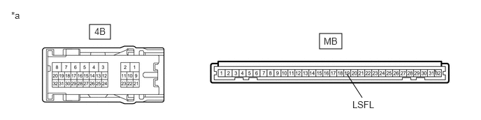
- INSPECT INSTRUMENT PANEL JUNCTION BLOCK ASSEMBLY
*a Component without harness connected
(Instrument Panel Junction Block Assembly)- - - Remove the main body ECU (multiplex network body ECU) from the instrument panel junction block assembly.
Refer to REMOVAL [12/2019 - 10/2022] , or refer to REMOVAL [10/2022 - 11/2023]
- Measure the resistance according to the value(s) in the table below.
Standard Resistance
Tester Connection Condition Specified Condition 4B-13 - MB-19 (LSFL) Always Below 1 Ω Result
Proceed to OK NG
Result:
OK
REPLACE MAIN BODY ECU (MULTIPLEX NETWORK BODY ECU). Refer to REMOVAL [12/2019 - 10/2022] , or refer to REMOVAL [10/2022 - 11/2023]
Result:
NG
REPLACE INSTRUMENT PANEL JUNCTION BLOCK ASSEMBLY. Refer to REMOVAL [12/2019 - 10/2022] , or refer to REMOVAL [10/2022 - 11/2023]
- Remove the main body ECU (multiplex network body ECU) from the instrument panel junction block assembly.
- INSPECT FRONT DOOR LOCK WITH MOTOR ASSEMBLY RH
Refer to INSPECTION [12/2019 - ]
Result
Proceed to OK NG Result:
NG
REPLACE FRONT DOOR LOCK WITH MOTOR ASSEMBLY RH. Refer to REMOVAL [12/2019 - 10/2022] , or refer to REMOVAL [10/2022 - 11/2023]
Result:
OK
See step 6
- CHECK HARNESS AND CONNECTOR (FRONT DOOR LOCK WITH MOTOR ASSEMBLY RH - INSTRUMENT PANEL JUNCTION BLOCK ASSEMBLY AND BODY GROUND)
- Disconnect the 4B instrument panel junction block assembly connector.
- Measure the resistance according to the value(s) in the table below.
Standard Resistance
Tester Connection Condition Specified Condition J14-7 (LSSR) - 4B-12 Always Below 1 Ω J14-7 (LSSR) or 4B-12 - Body ground Always 10 kΩ or higher J14-8 (E) - Body ground Always Below 1 Ω Result
Proceed to OK NG
Result:
NG
REPAIR OR REPLACE HARNESS OR CONNECTOR
Result:
OK
See step 7
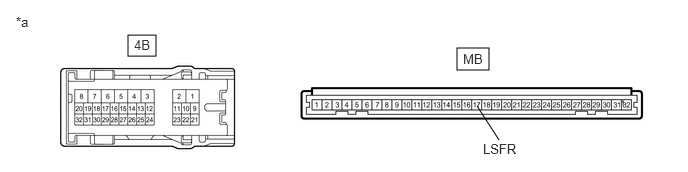
- INSPECT INSTRUMENT PANEL JUNCTION BLOCK ASSEMBLY
*a Component without harness connected
(Instrument Panel Junction Block Assembly)- - - Remove the main body ECU (multiplex network body ECU) from the instrument panel junction block assembly.
Refer to REMOVAL [12/2019 - 10/2022] , or refer to REMOVAL [10/2022 - 11/2023]
- Measure the resistance according to the value(s) in the table below.
Standard Resistance
Tester Connection Condition Specified Condition 4B-12 - MB-17 (LSFR) Always Below 1 Ω Result
Proceed to OK NG
Result:
OK
REPLACE MAIN BODY ECU (MULTIPLEX NETWORK BODY ECU). Refer to REMOVAL [12/2019 - 10/2022] , or refer to REMOVAL [10/2022 - 11/2023]
Result:
NG
REPLACE INSTRUMENT PANEL JUNCTION BLOCK ASSEMBLY. Refer to REMOVAL [12/2019 - 10/2022] , or refer to REMOVAL [10/2022 - 11/2023]
- Remove the main body ECU (multiplex network body ECU) from the instrument panel junction block assembly.
- INSPECT REAR DOOR LOCK WITH MOTOR ASSEMBLY LH
Refer to INSPECTION [12/2019 - ]
Result
Proceed to OK NG Result:
NG
REPLACE REAR DOOR LOCK WITH MOTOR ASSEMBLY LH. Refer to REMOVAL [12/2019 - 10/2022] , or refer to REMOVAL [10/2022 - 11/2023]
Result:
OK
See step 9
- CHECK HARNESS AND CONNECTOR (REAR DOOR LOCK WITH MOTOR ASSEMBLY LH - INSTRUMENT PANEL JUNCTION BLOCK ASSEMBLY AND BODY GROUND)
- Disconnect the 4B instrument panel junction block assembly connector.
- Measure the resistance according to the value(s) in the table below.
Standard Resistance
Tester Connection Condition Specified Condition K8-6 (LSSR) - 4B-14 Always Below 1 Ω K8-6 (LSSR) or 4B-14 - Body ground Always 10 kΩ or higher K8-9 (E) - Body ground Always Below 1 Ω Result
Proceed to OK NG
Result:
NG
REPAIR OR REPLACE HARNESS OR CONNECTOR
Result:
OK
See step 10
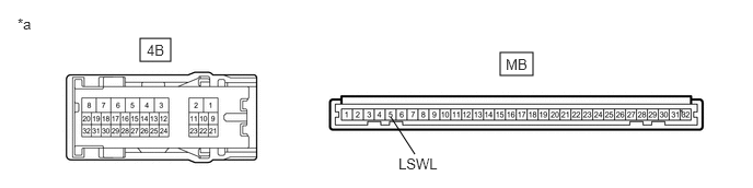
- INSPECT INSTRUMENT PANEL JUNCTION BLOCK ASSEMBLY
*a Component without harness connected
(Instrument Panel Junction Block Assembly)- - - Remove the main body ECU (multiplex network body ECU) from the instrument panel junction block assembly.
Refer to REMOVAL [12/2019 - 10/2022] , or refer to REMOVAL [10/2022 - 11/2023]
- Measure the resistance according to the value(s) in the table below.
Standard Resistance
Tester Connection Condition Specified Condition 4B-14 - MB-5 (LSWL) Always Below 1 Ω Result
Proceed to OK NG
Result:
OK
REPLACE MAIN BODY ECU (MULTIPLEX NETWORK BODY ECU). Refer to REMOVAL [12/2019 - 10/2022] , or refer to REMOVAL [10/2022 - 11/2023]
Result:
NG
REPLACE INSTRUMENT PANEL JUNCTION BLOCK ASSEMBLY. Refer to REMOVAL [12/2019 - 10/2022] , or refer to REMOVAL [10/2022 - 11/2023]
- Remove the main body ECU (multiplex network body ECU) from the instrument panel junction block assembly.
- INSPECT REAR DOOR LOCK WITH MOTOR ASSEMBLY RH
Refer to INSPECTION [12/2019 - ]
Result
Proceed to OK NG Result:
NG
REPLACE REAR DOOR LOCK WITH MOTOR ASSEMBLY RH. Refer to REMOVAL [12/2019 - 10/2022] , or refer to REMOVAL [10/2022 - 11/2023]
Result:
OK
See step 12
- CHECK HARNESS AND CONNECTOR (REAR DOOR LOCK WITH MOTOR ASSEMBLY RH - MAIN BODY ECU (MULTIPLEX NETWORK BODY ECU) AND BODY GROUND)
- Disconnect the H43 main body ECU (multiplex network body ECU) connector.
- Measure the resistance according to the value(s) in the table below.
Standard Resistance
Tester Connection Condition Specified Condition K3-6 (LSSR) - H43-17 (LSWR) Always Below 1 Ω K3-6 (LSSR) or H43-17 (LSWR) - Body ground Always 10 kΩ or higher K3-9 (E) - Body ground Always Below 1 Ω Result
Proceed to OK NG
Result:
OK
REPLACE MAIN BODY ECU (MULTIPLEX NETWORK BODY ECU). Refer to REMOVAL [12/2019 - 10/2022] , or refer to REMOVAL [10/2022 - 11/2023]
Result:
NG
REPAIR OR REPLACE HARNESS OR CONNECTOR