Inspection [12/2019 - 11/2023]: Procedure
WARNING: This page is about a different variant/trim than selected.
- INSPECT POWER SWITCH
- Check the resistance.
- Measure the resistance according to the value(s) in the table below.
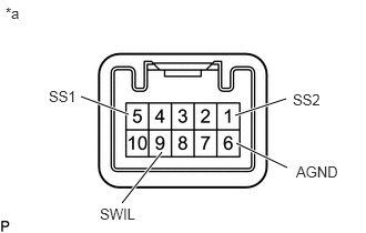
*a Component without harness connected
(Power switch)Standard Resistance
Tester Connection Condition Specified Condition 5 (SS1) - 6 (AGND)
1 (SS2) - 6 (AGND)Not pushed 10 kΩ or higher Pushed Below 1 Ω If the result is not as specified, replace the power switch.
- Measure the resistance according to the value(s) in the table below.
- Check the LED illumination.
- Apply battery voltage between the terminals of the power switch and check the illumination condition of the power switch indicator light.
OK
Condition Specified Condition Auxiliary battery positive (+) → Terminal 9 (SWIL)
Auxiliary battery negative (-) → Terminal 6 (AGND)Illuminates HINT:
- If the positive (+) lead and the negative (-) lead are incorrectly connected, the power switch indicator light will not illuminate.
- If the voltage is too low, the power switch indicator light will not illuminate.
If the result is not as specified, replace the power switch.
- Apply battery voltage between the terminals of the power switch and check the illumination condition of the power switch indicator light.
- Check the resistance.