DTC C2179: Tire Pressure Monitor ECU Communication Stop [12/2019 - 11/2023]: Procedure
- INSPECT MAIN BODY ECU (MULTIPLEX NETWORK BODY ECU) (OUTPUT WAVEFORM)
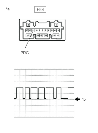
- Using an oscilloscope, check the waveform.NOTE:
With the connector connected, check from the backside of the connector.
*a Component with harness connected
(Main Body ECU (Multiplex Network Body ECU))*b GND OK
Tester Connection Tool Setting Range Condition Specified Condition H44-11 (PRG) - Body ground 5 V/DIV.5 ms./DIV. Ignition switch ON Waveform generation Result
Result Proceed to Waveform is as shown in the illustration. (Waveform alternates between 9.8 V or higher and 1.2 V or less) A Waveform does not change from 9.8 V or higher B Waveform does not change from 1.2 V or less C
Result:
A
REPLACE TIRE PRESSURE WARNING ECU AND RECEIVER. Refer to REMOVAL [12/2019 - 11/2023]
Result:
B
REPLACE MAIN BODY ECU (MULTIPLEX NETWORK BODY ECU). Refer to REMOVAL [12/2019 - 10/2022] , or refer to REMOVAL [10/2022 - 11/2023]
Result:
C
See step 2
- Using an oscilloscope, check the waveform.
- CHECK TERMINAL VOLTAGE (TIRE PRESSURE WARNING ECU AND RECEIVER OUTPUT)
- Disconnect the H44 main body ECU (multiplex network body ECU) connector.
- Measure the voltage according to the value(s) in the table below.
Standard Voltage
Tester Connection Condition Specified Condition H44-11 (PRG) - Body ground Ignition switch ON 9.8 V or higher Result
Proceed to OK NG
Result:
OK
REPLACE MAIN BODY ECU (MULTIPLEX NETWORK BODY ECU). Refer to REMOVAL [12/2019 - 10/2022] , or refer to REMOVAL [10/2022 - 11/2023]
Result:
NG
See step 3
- CHECK HARNESS AND CONNECTOR (TIRE PRESSURE WARNING ECU AND RECEIVER - MAIN BODY ECU (MULTIPLEX NETWORK BODY ECU))
- Turn the ignition switch off.
- Disconnect the M51 tire pressure warning ECU and receiver connector.
- Measure the resistance according to the value(s) in the table below.
Standard Resistance
Tester Connection Condition Specified Condition M51-5 (PRG) - H44-11 (PRG) Always Below 1 Ω M51-5 (PRG) or H44-11 (PRG) - Body ground Always 10 kΩ or higher Result
Proceed to OK NG
Result:
NG
REPAIR OR REPLACE HARNESS OR CONNECTOR
Result:
OK
See step 4
- CHECK HARNESS AND CONNECTOR (POWER SUPPLY - TIRE PRESSURE WARNING ECU AND RECEIVER)
- Measure the voltage according to the value(s) in the table below.
Standard Voltage
Tester Connection Condition Specified Condition M51-7 (+B) - Body ground Always 10 to 16 V M51-1 (IG) - Body ground Ignition switch ON 10 to 16 V Result
Result Proceed to OK A NG (w/ Stop and Start System) B NG (w/o Stop and Start System) C
Result:
A
REPLACE TIRE PRESSURE WARNING ECU AND RECEIVER. Refer to REMOVAL [12/2019 - 11/2023]
Result:
B
INSPECT STOP AND START SYSTEM (BACKUP BOOST CONVERTER CIRCUIT). Refer to Backup Boost Converter Circuit [12/2019 - 10/2022] , or refer to Backup Boost Converter Circuit [10/2022 - 11/2023]
Result:
C
REPAIR OR REPLACE HARNESS OR CONNECTOR
- Measure the voltage according to the value(s) in the table below.