DTC B1206-87: P/W Master SW System Missing Message; DTC B1273-87: Sliding Roof System Missing Message; DTC B2321-87: D-Door P/W System Missing Message; DTC B2322-87: P-Door P/W System Missing Message; DTC B2323-87: RR-Door P/W System Missing Message; DTC B2324-87: RL-Door P/W System Missing Message; DTC B2329-87: Sunshade System Missing Message [11/2023 - ]: Procedure
- CLEAR DTC
Result:
NEXT
See step 2
- CHECK FOR DTC
- Check for DTCs.
Body Electrical > Main Body > Trouble Codes
Result
Result Proceed to DTCs are not output A B1206-87, B1273-87*1*2, B2321-87, B2322-87, B2323-87, B2324-87 and B2329-87*2 are output B B1206-87, B1273-87*1*2, B2321-87, B2322-87 and B2329-87*2 are output C B2323-87 and B2324-87 are output D B1206-87 and B2321-87 are output E B1273-87 and B2329-87 are output*2 F Only B1206-87 is output G Only B1273-87 is output*1*2 H Only B2321-87 is output I Only B2322-87 is output J Only B2323-87 is output K Only B2324-87 is output L Only B2329-87 is output*2 M *1: w/ Sliding Roof System
*2: w/ Panoramic Moon Roof System
Result:
A
USE SIMULATION METHOD TO CHECK. Refer to HOW TO PROCEED WITH TROUBLESHOOTING [12/2019 - ]
Result:
C
See step 4
Result:
D
See step 6
Result:
E
See step 8
Result:
F
See step 9
Result:
G
See step 10
Result:
H
See step 12
Result:
I
See step 15
Result:
J
See step 19
Result:
K
See step 22
Result:
L
See step 25
Result:
M
See step 28
Result:
B
See step 3
- Check for DTCs.
- INSPECT POWER DISTRIBUTION BOX ASSEMBLY
Pre-procedure1
- Remove the power distribution box assembly.
HINT:
Refer to REMOVAL [11/2023 - ]
- Remove the main body ECU (multiplex network body ECU) from the power distribution box assembly.
Procedure1
- Measure the resistance according to the value(s) in the table below.
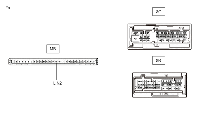
*a Component without harness connected
(Power Distribution Box Assembly)- - HINT:
This inspection is to check the LIN communication line in the power distribution box assembly that connects the wire harness to the built-in main body ECU (multiplex network body ECU).
Standard Resistance
Tester Connection Condition Specified Condition MB-15 (LIN2) - 8B-37 or 8G-17 Always Below 1 Ω Result
Proceed to OK NG Post-procedure1
- None
Result:
OK
REPLACE MAIN BODY ECU (MULTIPLEX NETWORK BODY ECU). Refer to REMOVAL [11/2023 - ]
Result:
NG
REPLACE POWER DISTRIBUTION BOX ASSEMBLY. Refer to REMOVAL [11/2023 - ]
- Remove the power distribution box assembly.
- INSPECT POWER DISTRIBUTION BOX ASSEMBLY
Pre-procedure1
- Remove the power distribution box assembly.
HINT:
Refer to REMOVAL [11/2023 - ]
- Remove the main body ECU (multiplex network body ECU) from the power distribution box assembly.
Procedure1
- Measure the resistance according to the value(s) in the table below.
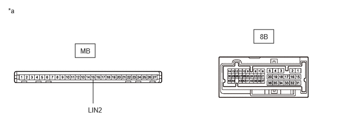
*a Component without harness connected
(Power Distribution Box Assembly)- - HINT:
This inspection is to check the LIN communication line in the power distribution box assembly that connects the wire harness to the built-in main body ECU (multiplex network body ECU).
Standard Resistance
Tester Connection Condition Specified Condition MB-15 (LIN2) - 8B-37 Always Below 1 Ω Result
Proceed to OK NG Post-procedure1
- None
Result:
NG
REPLACE POWER DISTRIBUTION BOX ASSEMBLY. Refer to REMOVAL [11/2023 - ]
Result:
OK
See step 5
- Remove the power distribution box assembly.
- CHECK HARNESS AND CONNECTOR (POWER DISTRIBUTION BOX ASSEMBLY - MULTIPLEX NETWORK MASTER SWITCH ASSEMBLY)
Pre-procedure1
- Disconnect the J18 multiplex network master switch assembly connector.
Procedure1
- Measure the resistance according to the value(s) in the table below.NOTE:
Make sure that each ECU is in sleep mode before performing the inspection. To enter sleep mode, turn the ignition switch from ON to off and wait for 180 seconds or more without operating any switches.
Standard Resistance
Tester Connection Condition Specified Condition 8B-37 - J18-17 (LIN1) Ignition switch off Below 1 Ω Result
Proceed to OK NG Post-procedure1
- None
Result:
OK
REPLACE MAIN BODY ECU (MULTIPLEX NETWORK BODY ECU). Refer to REMOVAL [11/2023 - ]
Result:
NG
REPAIR OR REPLACE HARNESS OR CONNECTOR
- Disconnect the J18 multiplex network master switch assembly connector.
- INSPECT POWER DISTRIBUTION BOX ASSEMBLY
Pre-procedure1
- Remove the power distribution box assembly.
HINT:
Refer to REMOVAL [11/2023 - ]
- Remove the main body ECU (multiplex network body ECU) from the power distribution box assembly.
Procedure1
- Measure the resistance according to the value(s) in the table below.
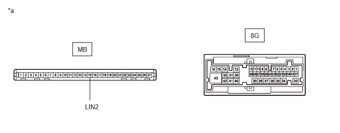
*a Component without harness connected
(Power Distribution Box Assembly)- - HINT:
This inspection is to check the LIN communication line in the power distribution box assembly that connects the wire harness to the built-in main body ECU (multiplex network body ECU).
Standard Resistance
Tester Connection Condition Specified Condition MB-15 (LIN2) - 8G-17 Always Below 1 Ω Result
Proceed to OK NG Post-procedure1
- None
Result:
NG
REPLACE POWER DISTRIBUTION BOX ASSEMBLY. Refer to REMOVAL [11/2023 - ]
Result:
OK
See step 7
- Remove the power distribution box assembly.
- CHECK HARNESS AND CONNECTOR (POWER DISTRIBUTION BOX ASSEMBLY - POWER WINDOW REGULATOR MOTOR ASSEMBLY (REAR LH DOOR))
Pre-procedure1
- Disconnect the K9 power window regulator motor assembly (rear LH door) connector.
Procedure1
- Measure the resistance according to the value(s) in the table below.NOTE:
Make sure that each ECU is in sleep mode before performing the inspection. To enter sleep mode, turn the ignition switch from ON to off and wait for 180 seconds or more without operating any switches.
Standard Resistance
Tester Connection Condition Specified Condition 8G-17 - K9-9 (LIN) Ignition switch off Below 1 Ω Result
Proceed to OK NG Post-procedure1
- None
Result:
OK
REPLACE MAIN BODY ECU (MULTIPLEX NETWORK BODY ECU). Refer to REMOVAL [11/2023 - ]
Result:
NG
REPAIR OR REPLACE HARNESS OR CONNECTOR
- Disconnect the K9 power window regulator motor assembly (rear LH door) connector.
- CHECK HARNESS AND CONNECTOR (POWER DISTRIBUTION BOX ASSEMBLY - MULTIPLEX NETWORK MASTER SWITCH ASSEMBLY)
Pre-procedure1
- Disconnect the 8B power distribution box assembly connector.
- Disconnect the J18 multiplex network master switch assembly connector.
Procedure1
- Measure the resistance according to the value(s) in the table below.NOTE:
Make sure that each ECU is in sleep mode before performing the inspection. To enter sleep mode, turn the ignition switch from ON to off and wait for 180 seconds or more without operating any switches.
Standard Resistance
Tester Connection Condition Specified Condition 8B-37 - J18-17 (LIN1) Ignition switch off Below 1 Ω Result
Proceed to OK NG Post-procedure1
- None
Result:
OK
REPLACE MAIN BODY ECU (MULTIPLEX NETWORK BODY ECU). Refer to REMOVAL [11/2023 - ]
Result:
NG
REPAIR OR REPLACE HARNESS OR CONNECTOR
- CHECK HARNESS AND CONNECTOR (POWER DISTRIBUTION BOX ASSEMBLY - SLIDING ROOF ECU (SLIDING ROOF DRIVE GEAR ASSEMBLY))
Pre-procedure1
- Disconnect the 8B power distribution box assembly connector.
- Disconnect the R19 sliding roof ECU (sliding roof drive gear assembly) connector.
Procedure1
- Measure the resistance according to the value(s) in the table below.
Standard Resistance
Tester Connection Condition Specified Condition 8B-37 - R19-11 (MPX1) Ignition switch off Below 1 Ω Result
Proceed to OK NG Post-procedure1
- None
Result:
OK
REPLACE MAIN BODY ECU (MULTIPLEX NETWORK BODY ECU). Refer to REMOVAL [11/2023 - ]
Result:
NG
REPAIR OR REPLACE HARNESS OR CONNECTOR
- CHECK HARNESS AND CONNECTOR (MULTIPLEX NETWORK MASTER SWITCH ASSEMBLY - AUXILIARY BATTERY)
Pre-procedure1
- Disconnect the J18 multiplex network master switch assembly connector.
Procedure1
- Measure the voltage according to the value(s) in the table below.
Standard Voltage
Tester Connection Condition Specified Condition J18-11 (B) - Body ground Ignition switch off 11 to 14 V Result
Proceed to OK NG Post-procedure1
- None
Result:
NG
REPAIR OR REPLACE HARNESS OR CONNECTOR
Result:
OK
See step 11
- Disconnect the J18 multiplex network master switch assembly connector.
- CHECK HARNESS AND CONNECTOR (MULTIPLEX NETWORK MASTER SWITCH ASSEMBLY - BODY GROUND)
Pre-procedure1
- Disconnect the J18 multiplex network master switch assembly connector.
Procedure1
- Measure the resistance according to the value(s) in the table below.
Standard Resistance
Tester Connection Condition Specified Condition J18-12 (GND) - Body ground Always Below 1 Ω Result
Proceed to OK NG Post-procedure1
- None
Result:
OK
REPLACE MULTIPLEX NETWORK MASTER SWITCH ASSEMBLY. Refer to REMOVAL [12/2019 - ]
Result:
NG
REPAIR OR REPLACE HARNESS OR CONNECTOR
- Disconnect the J18 multiplex network master switch assembly connector.
- CHECK HARNESS AND CONNECTOR (POWER DISTRIBUTION BOX ASSEMBLY - SLIDING ROOF ECU (SLIDING ROOF DRIVE GEAR ASSEMBLY))
Pre-procedure1
- Disconnect the 8B power distribution box assembly connector.
- Disconnect the R2*1 or R19*2 sliding roof ECU (sliding roof drive gear assembly) connector.
- *1: w/ Sliding Roof System
- *2: w/ Panoramic Moon Roof System
Procedure1
- Measure the resistance according to the value(s) in the table below.
Standard Resistance
W/ SLIDING ROOF SYSTEMTester Connection Condition Specified Condition 8B-37 - R2-7 (MPX1) Ignition switch off Below 1 Ω W/ PANORAMIC MOON ROOF SYSTEMTester Connection Condition Specified Condition 8B-37 - R19-11 (MPX1) Ignition switch off Below 1 Ω Result
Proceed to OK NG Post-procedure1
- None
Result:
NG
REPAIR OR REPLACE HARNESS OR CONNECTOR
Result:
OK
See step 13
- CHECK HARNESS AND CONNECTOR (SLIDING ROOF ECU (SLIDING ROOF DRIVE GEAR ASSEMBLY) - AUXILIARY BATTERY)
- Measure the voltage according to the value(s) in the table below.
Standard Voltage
W/ SLIDING ROOF SYSTEMTester Connection Condition Specified Condition R2-1 (B) - Body ground Ignition switch off 11 to 14 V W/ PANORAMIC MOON ROOF SYSTEMTester Connection Condition Specified Condition R19-8 (B) - Body ground Ignition switch off 11 to 14 V Result
Proceed to OK NG
Result:
NG
REPAIR OR REPLACE HARNESS OR CONNECTOR
Result:
OK
See step 14
- Measure the voltage according to the value(s) in the table below.
- CHECK HARNESS AND CONNECTOR (SLIDING ROOF ECU (SLIDING ROOF DRIVE GEAR ASSEMBLY) - BODY GROUND)
- Measure the resistance according to the value(s) in the table below.
Standard Resistance
W/ SLIDING ROOF SYSTEMTester Connection Condition Specified Condition R2-2 (E) - Body ground Always Below 1 Ω W/ PANORAMIC MOON ROOF SYSTEMTester Connection Condition Specified Condition R19-12 (E) - Body ground Always Below 1 Ω Result
Proceed to OK NG
Result:
OK
REPLACE SLIDING ROOF ECU (SLIDING ROOF DRIVE GEAR ASSEMBLY)
for Moon Roof: Refer to DISASSEMBLY [12/2019 - ]
for Panoramic Moon Roof: Refer to DISASSEMBLY [12/2019 - ]
Result:
NG
REPAIR OR REPLACE HARNESS OR CONNECTOR
- Measure the resistance according to the value(s) in the table below.
- INSPECT MULTIPLEX NETWORK MASTER SWITCH ASSEMBLY
Pre-procedure1
- Remove the multiplex network master switch assembly.
HINT:
Refer to INSPECTION [12/2019 - ]
Procedure1
- Measure the resistance according to the value(s) in the table below.
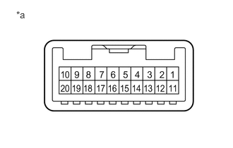
*a Component without harness connected
(Multiplex Network Master Switch Assembly)Standard Resistance
Tester Connection Condition Specified Condition 16 - 17 Always Below 1 Ω Result
Proceed to OK NG Post-procedure1
- None
Result:
NG
REPLACE MULTIPLEX NETWORK MASTER SWITCH ASSEMBLY. Refer to REMOVAL [12/2019 - ]
Result:
OK
See step 16
- Remove the multiplex network master switch assembly.
- CHECK HARNESS AND CONNECTOR (MULTIPLEX NETWORK MASTER SWITCH ASSEMBLY - POWER WINDOW REGULATOR MOTOR ASSEMBLY (DRIVER DOOR))
Pre-procedure1
- Disconnect the J24 power window regulator motor assembly (driver door) connector.
Procedure1
- Measure the resistance according to the value(s) in the table below.
Standard Resistance
Tester Connection Condition Specified Condition J18-16 (LIN2) - J24-9 (LIN) Always Below 1 Ω Result
Proceed to OK NG Post-procedure1
- None
Result:
NG
REPAIR OR REPLACE HARNESS OR CONNECTOR
Result:
OK
See step 17
- Disconnect the J24 power window regulator motor assembly (driver door) connector.
- CHECK HARNESS AND CONNECTOR (POWER WINDOW REGULATOR MOTOR ASSEMBLY (DRIVER DOOR) - AUXILIARY BATTERY)
- Measure the voltage according to the value(s) in the table below.
Standard Voltage
Tester Connection Condition Specified Condition J24-2 (B) - Body ground Ignition switch off 11 to 14 V Result
Proceed to OK NG
Result:
NG
REPAIR OR REPLACE HARNESS OR CONNECTOR
Result:
OK
See step 18
- Measure the voltage according to the value(s) in the table below.
- CHECK HARNESS AND CONNECTOR (POWER WINDOW REGULATOR MOTOR ASSEMBLY (DRIVER DOOR) - BODY GROUND)
- Measure the resistance according to the value(s) in the table below.
Standard Resistance
Tester Connection Condition Specified Condition J24-1 (GND) - Body ground Always Below 1 Ω Result
Proceed to OK NG
Result:
OK
REPLACE POWER WINDOW REGULATOR MOTOR ASSEMBLY (DRIVER DOOR). Refer to REMOVAL [11/2023 - ]
Result:
NG
REPAIR OR REPLACE HARNESS OR CONNECTOR
- Measure the resistance according to the value(s) in the table below.
- CHECK HARNESS AND CONNECTOR (POWER DISTRIBUTION BOX ASSEMBLY - POWER WINDOW REGULATOR MOTOR ASSEMBLY (FRONT PASSENGER DOOR))
Pre-procedure1
- Disconnect the 8B power distribution box assembly connector.
- Disconnect the J8 power window regulator motor assembly (front passenger door) connector.
Procedure1
- Measure the resistance according to the value(s) in the table below.NOTE:
Make sure that each ECU is in sleep mode before performing the inspection. To enter sleep mode, turn the ignition switch from ON to off and wait for 180 seconds or more without operating any switches.
Standard Resistance
Tester Connection Condition Specified Condition 8B-37 - J8-9 (LIN) Ignition switch off Below 1 Ω Result
Proceed to OK NG Post-procedure1
- None
Result:
NG
REPAIR OR REPLACE HARNESS OR CONNECTOR
Result:
OK
See step 20
- CHECK HARNESS AND CONNECTOR (POWER WINDOW REGULATOR MOTOR ASSEMBLY (FRONT PASSENGER DOOR) - AUXILIARY BATTERY)
- Measure the voltage according to the value(s) in the table below.
Standard Voltage
Tester Connection Condition Specified Condition J8-2 (B) - Body ground Ignition switch off 11 to 14 V Result
Proceed to OK NG
Result:
NG
REPAIR OR REPLACE HARNESS OR CONNECTOR
Result:
OK
See step 21
- Measure the voltage according to the value(s) in the table below.
- CHECK HARNESS AND CONNECTOR (POWER WINDOW REGULATOR MOTOR ASSEMBLY (FRONT PASSENGER DOOR) - BODY GROUND)
- Measure the resistance according to the value(s) in the table below.
Standard Resistance
Tester Connection Condition Specified Condition J8-1 (GND) - Body ground Always Below 1 Ω Result
Proceed to OK NG
Result:
OK
REPLACE POWER WINDOW REGULATOR MOTOR ASSEMBLY (FRONT PASSENGER DOOR). Refer to REMOVAL [11/2023 - ]
Result:
NG
REPAIR OR REPLACE HARNESS OR CONNECTOR
- Measure the resistance according to the value(s) in the table below.
- CHECK HARNESS AND CONNECTOR (POWER DISTRIBUTION BOX ASSEMBLY - POWER WINDOW REGULATOR MOTOR ASSEMBLY (REAR RH DOOR))
Pre-procedure1
- Disconnect the 8G power distribution box assembly connector.
- Disconnect the K4 power window regulator motor assembly (rear RH Door) connector.
Procedure1
- Measure the resistance according to the value(s) in the table below.NOTE:
Make sure that each ECU is in sleep mode before performing the inspection. To enter sleep mode, turn the ignition switch from ON to off and wait for 180 seconds or more without operating any switches.
Standard Resistance
Tester Connection Condition Specified Condition 8G-17 - K4-9 (LIN) Ignition switch off Below 1 Ω Result
Proceed to OK NG Post-procedure1
- None
Result:
NG
REPAIR OR REPLACE HARNESS OR CONNECTOR
Result:
OK
See step 23
- CHECK HARNESS AND CONNECTOR (POWER WINDOW REGULATOR MOTOR ASSEMBLY (REAR RH DOOR) - AUXILIARY BATTERY)
- Measure the voltage according to the value(s) in the table below.
Standard Voltage
Tester Connection Condition Specified Condition K4-2 (B) - Body ground Ignition switch off 11 to 14 V Result
Proceed to OK NG
Result:
NG
REPAIR OR REPLACE HARNESS OR CONNECTOR
Result:
OK
See step 24
- Measure the voltage according to the value(s) in the table below.
- CHECK HARNESS AND CONNECTOR (POWER WINDOW REGULATOR MOTOR ASSEMBLY (REAR RH DOOR) - BODY GROUND)
- Measure the resistance according to the value(s) in the table below.
Standard Resistance
Tester Connection Condition Specified Condition K4-1 (GND) - Body ground Always Below 1 Ω Result
Proceed to OK NG
Result:
OK
REPLACE POWER WINDOW REGULATOR MOTOR ASSEMBLY (REAR RH DOOR). Refer to REMOVAL [11/2023 - ]
Result:
NG
REPAIR OR REPLACE HARNESS OR CONNECTOR
- Measure the resistance according to the value(s) in the table below.
- CHECK HARNESS AND CONNECTOR (POWER DISTRIBUTION BOX ASSEMBLY - POWER WINDOW REGULATOR MOTOR ASSEMBLY (REAR LH DOOR))
Pre-procedure1
- Disconnect the 8G power distribution box assembly connector.
- Disconnect the K9 power window regulator motor assembly (rear LH door) connector.
Procedure1
- Measure the resistance according to the value(s) in the table below.NOTE:
Make sure that each ECU is in sleep mode before performing the inspection. To enter sleep mode, turn the ignition switch from ON to off and wait for 180 seconds or more without operating any switches.
Standard Resistance
Tester Connection Condition Specified Condition 8G-17 - K9-9 (LIN) Ignition switch off Below 1 Ω Result
Proceed to OK NG Post-procedure1
- None
Result:
NG
REPAIR OR REPLACE HARNESS OR CONNECTOR
Result:
OK
See step 26
- CHECK HARNESS AND CONNECTOR (POWER WINDOW REGULATOR MOTOR ASSEMBLY (REAR LH DOOR) - AUXILIARY BATTERY)
- Measure the voltage according to the value(s) in the table below.
Standard Voltage
Tester Connection Condition Specified Condition K9-2 (B) - Body ground Ignition switch off 11 to 14 V Result
Proceed to OK NG
Result:
NG
REPAIR OR REPLACE HARNESS OR CONNECTOR
Result:
OK
See step 27
- Measure the voltage according to the value(s) in the table below.
- CHECK HARNESS AND CONNECTOR (POWER WINDOW REGULATOR MOTOR ASSEMBLY (REAR LH DOOR) - BODY GROUND)
- Measure the resistance according to the value(s) in the table below.
Standard Resistance
Tester Connection Condition Specified Condition K9-1 (GND) - Body ground Always Below 1 Ω Result
Proceed to OK NG
Result:
OK
REPLACE POWER WINDOW REGULATOR MOTOR ASSEMBLY (REAR LH DOOR). Refer to REMOVAL [11/2023 - ]
Result:
NG
REPAIR OR REPLACE HARNESS OR CONNECTOR
- Measure the resistance according to the value(s) in the table below.
- CHECK HARNESS AND CONNECTOR (POWER DISTRIBUTION BOX ASSEMBLY - ROOF SUNSHADE ECU (SLIDING ROOF DRIVE GEAR ASSEMBLY))
Pre-procedure1
- Disconnect the 8B power distribution box assembly connector.
- Disconnect the R20 roof sunshade ECU (sliding roof drive gear assembly) connector.
Procedure1
- Measure the resistance according to the value(s) in the table below.
Standard Resistance
Tester Connection Condition Specified Condition 8B-37 - R20-11 (MPX1) Ignition switch off Below 1 Ω Result
Proceed to OK NG Post-procedure1
- None
Result:
NG
REPAIR OR REPLACE HARNESS OR CONNECTOR
Result:
OK
See step 29
- CHECK HARNESS AND CONNECTOR (ROOF SUNSHADE ECU (SLIDING ROOF DRIVE GEAR ASSEMBLY) - AUXILIARY BATTERY)
- Measure the voltage according to the value(s) in the table below.
Standard Voltage
Tester Connection Condition Specified Condition R20-8 (B) - Body ground Ignition switch off 11 to 14 V Result
Proceed to OK NG
Result:
NG
REPAIR OR REPLACE HARNESS OR CONNECTOR
Result:
OK
See step 30
- Measure the voltage according to the value(s) in the table below.
- CHECK HARNESS AND CONNECTOR (ROOF SUNSHADE ECU (SLIDING ROOF DRIVE GEAR ASSEMBLY) - BODY GROUND)
- Measure the resistance according to the value(s) in the table below.
Standard Resistance
Tester Connection Condition Specified Condition R20-12 (E) - Body ground Always Below 1 Ω Result
Proceed to OK NG
Result:
OK
REPLACE ROOF SUNSHADE ECU (SLIDING ROOF DRIVE GEAR ASSEMBLY). Refer to DISASSEMBLY [12/2019 - ]
Result:
NG
REPAIR OR REPLACE HARNESS OR CONNECTOR
- Measure the resistance according to the value(s) in the table below.