Installation [12/2019 - ]: Procedure
- TEMPORARILY INSTALL SLIDING ROOF HOUSING ASSEMBLY
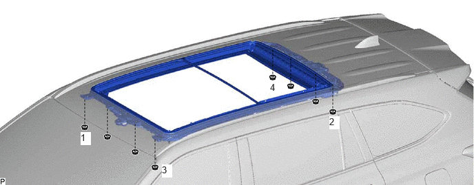
- Temporarily install the sliding roof housing assembly with the 8 nuts.
- Tighten the 4 nuts.
 Courtesy of © TOYOTA, LICENSE AGREEMENT TMS1002
HINT:
Tighten the bolts in the order shown in the illustration.
Torque: 5.5 N.m (56 kgf/cm, 49 in.lbf)
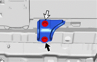
- INSTALL REAR SLIDING ROOF HOUSING MOUNTING BRACKET LH
- INSTALL REAR SLIDING ROOF HOUSING MOUNTING BRACKET RH
HINT:
Use the same procedure as for the LH side.
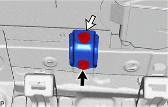
- INSTALL FRONT SLIDING ROOF HOUSING MOUNTING BRACKET LH
- Install the front sliding roof housing mounting bracket LH with the 2 bolts.

Bolt (A) 
Bolt (B) HINT:
- Use the same procedure for the front side and rear side.
- The bolts must be tightened in the order of (A) then (B).
Bolt (A)
Torque: 8.0 N.m (82 kgf/cm, 71 in.lbf)
Bolt (B)
Torque: 5.5 N.m (56 kgf/cm, 49 in.lbf)
- Install the front sliding roof housing mounting bracket LH with the 2 bolts.
- INSTALL FRONT SLIDING ROOF HOUSING MOUNTING BRACKET RH
HINT:
Use the same procedure as for the LH side.
- INSTALL SLIDING ROOF HOUSING ASSEMBLY
- Tighten the 4 nuts to install the sliding roof housing assembly.
Torque: 5.5 N.m (56 kgf/cm, 49 in.lbf)
- Tighten the 4 nuts to install the sliding roof housing assembly.
- INSTALL CENTER SLIDING ROOF HOUSING MOUNTING BRACKET LH
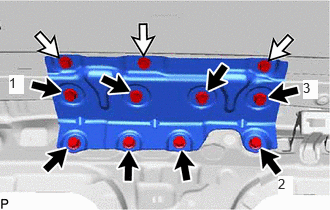
- Temporarily install the center sliding roof housing mounting bracket LH with the 11 bolts.
 Courtesy of © TOYOTA, LICENSE AGREEMENT TMS1002
Bolt (A) Bolt (B) - Tighten the 3 bolts.
HINT:
Tighten the 3 bolts in the order shown in the illustration.
Torque: 18.5 N.m (189 kgf/cm, 14 ft.lbf)
- Tighten the center sliding roof housing mounting bracket LH with the 8 bolts.
HINT:
The bolts must be tightened in the order of (A) then (B).
Bolt (A)
Torque: 18.5 N.m (189 kgf/cm, 14 ft.lbf)
Bolt (B)
Torque: 5.5 N.m (56 kgf/cm, 49 in.lbf)
- Temporarily install the center sliding roof housing mounting bracket LH with the 11 bolts.
- INSTALL CENTER SLIDING ROOF HOUSING MOUNTING BRACKET RH
HINT:
Use the same procedure as for the LH side.
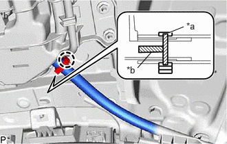
- CONNECT SLIDING ROOF DRAIN HOSE
- for Clamp Type:
*a Clamp *b Marking - Connect the sliding roof drain hose.
HINT:
- Slide the hose to the base of the drain pipe.
- Use the same procedure for the other 3 sliding roof drain hoses.
- Engage the claw to secure the sliding roof drain hose.
HINT:
- Make sure that the clamp is on the marking or between the marking and hose end.
- Use the same procedure for the other 3 sliding roof drain hoses.
- Connect the sliding roof drain hose.
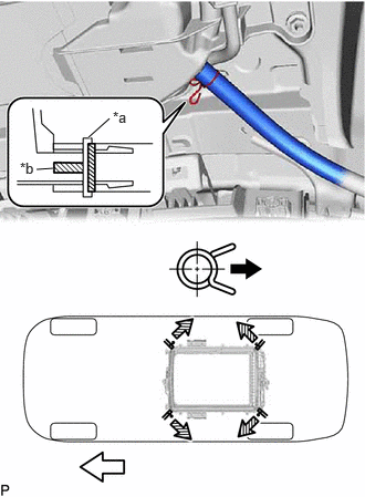
- for Clip Type:
*a Clip *b Marking Outside Front Side - Expand the clip and connect the sliding roof drain hose.
HINT:
- Slide the hose to the base of the drain pipe.
- Use the same procedure for the other 3 sliding roof drain hoses.
- Release the clip to secure the sliding roof drain hose.NOTE:
The clip must face toward the outside of the vehicle and also be above the lower surface of the sliding roof housing assembly when installing the sliding roof drain hoses.
HINT:
- Make sure that the clip is on the marking or between the marking and hose end.
- Use the same procedure for the other 3 sliding roof drain hoses.
- Expand the clip and connect the sliding roof drain hose.
- for Clamp Type:
- INSTALL CURTAIN SHIELD AIRBAG ASSEMBLY LH
Refer to INSTALLATION [12/2019 - 10/2022] , or refer to INSTALLATION [10/2022 - 11/2023] , or refer to INSTALLATION [11/2023 - ]
- INSTALL CURTAIN SHIELD AIRBAG ASSEMBLY RH
HINT:
Use the same procedure as for the LH side.
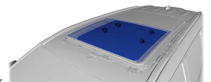
- INSTALL NO. 2 SLIDING ROOF GLASS SUB-ASSEMBLY
- Using a T25 "TORX" socket wrench, temporarily install the No. 2 sliding roof glass sub-assembly with the 4 screws.
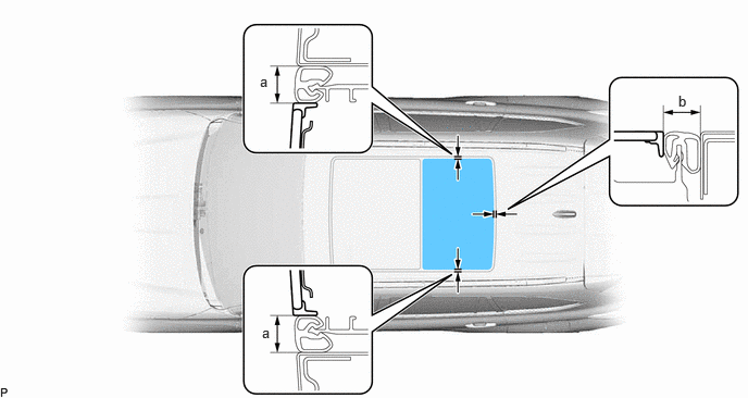
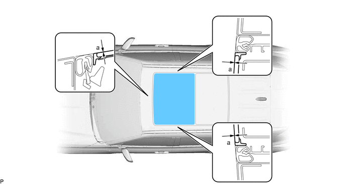
- Perform a level check.
- Check the difference in level "a" between the roof panel and the upper surface of the No. 2 sliding roof glass sub-assembly.
HINT:
"+" represents the condition that the glass is above the panel level. "-" represents the condition that the glass is below the panel level.
Standard
Area Measurement a 0 (+) 2.0 mm (0 (+) 0.0787 in.)
0 - 2.0 mm (0 - 0.0787 in.)
- Check the difference in level "a" between the roof panel and the upper surface of the No. 2 sliding roof glass sub-assembly.
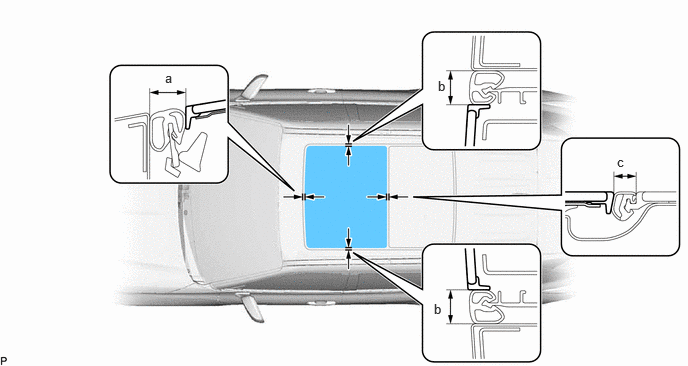
- Perform a gap check.
- After adjusting the No. 2 sliding roof glass sub-assembly, using a T25 "TORX" socket wrench, tighten the 4 screws to install the No. 2 sliding roof glass sub-assembly.
Torque: 4.0 N.m (41 kgf/cm, 35 in.lbf)
- INSTALL NO. 1 SLIDING ROOF GLASS SUB-ASSEMBLY
- Using a T25 "TORX" socket wrench, temporarily install the No. 1 sliding roof glass sub-assembly with the 4 screws.
- Perform a level check.
- Check the difference in level "a" between the roof panel and the upper surface of the No. 1 sliding roof glass sub-assembly when the No. 1 sliding roof glass sub-assembly is fully closed.
HINT:
"+" represents the condition that the glass is above the panel level. "-" represents the condition that the glass is below the panel level.
Standard
Area Measurement a 0 (+) 2.0 mm (0 (+) 0.0787 in.)
0 - 2.0 mm (0 - 0.0787 in.)
- Check the difference in level "a" between the roof panel and the upper surface of the No. 1 sliding roof glass sub-assembly when the No. 1 sliding roof glass sub-assembly is fully closed.
- Perform a gap check.
- After adjusting the No. 1 sliding roof glass sub-assembly, using a T25 "TORX" socket wrench, tighten the 4 screws.
Torque: 4.0 N.m (41 kgf/cm, 35 in.lbf)
- Check for water leak.
- After adjusting the No. 1 sliding roof glass sub-assembly and No. 2 sliding roof glass sub-assembly, check for water leakage into the vehicle interior.
- If there are any leaks, readjust the No. 1 sliding roof glass sub-assembly and No. 2 sliding roof glass sub-assembly.
- Install the roof headlining assembly.
Refer to INSTALLATION [12/2019 - 10/2022] , or refer to INSTALLATION [10/2022 - ]
- Open the No. 1 sliding roof glass sub-assembly to a position where the 2 screws (A) can be installed.
- Using a T25 "TORX" socket wrench, install the No. 1 sliding roof glass sub-assembly with the 2 screws.
Torque: 4.0 N.m (41 kgf/cm, 35 in.lbf)
- Fully close the No. 1 sliding roof glass sub-assembly.
- Using a T25 "TORX" socket wrench, temporarily install the No. 1 sliding roof glass sub-assembly with the 4 screws.
- INSTALL SLIDING ROOF SIDE GARNISH LH
- INSTALL SLIDING ROOF SIDE GARNISH RH
HINT:
Use the same procedure as for the LH side.
- INITIALIZE PANORAMIC MOON ROOF SYSTEM
Refer to INITIALIZATION [12/2019 - ]
- CHECK PANORAMIC MOON ROOF SYSTEM
Refer to OPERATION CHECK [12/2019 - ]