DTC B2285: Steering Lock Position Signal Circuit Malfunction [12/2019 - 10/2021]: Procedure
- CHECK FOR DTC
- Check for DTCs.
Body Electrical > Smart Key > Trouble Codes
HINT:
- If the steering cannot be unlocked, the ignition switch cannot be turned to ON and the engine cannot be started.
- If LIN communication is not available, the steering cannot be locked or unlocked.
OK
LIN communication system DTC B2785 is not output simultaneously.
Result
Proceed to OK NG
Result:
NG
GO TO DTC B2785. Refer to DTC B2785: Communication Malfunction between ECUs Connected by LIN [12/2019 - 10/2021]
Result:
OK
See step 2
- Check for DTCs.
- READ VALUE USING GTS (STEERING UNLOCK SWITCH)
- Read the Data List according to the display on the GTS.
Body Electrical > Power Source Control > Data List
Tester Display Measurement Item Range Normal Condition Diagnostic Note Steering Unlock Switch State of steering unlock sensor signal output from steering lock ECU (steering lock actuator or upper bracket assembly) OFF or ON OFF: Steering locked
ON: Steering unlocked- When the shift lever is in P and the ignition switch is off, if any door is opened or closed, the steering is locked.
- When the electrical key transmitter sub-assembly is in the cabin and the ignition switch is turned to ACC or ON, the steering unlocks.
- The engine cannot be started when the steering unlock signal is off.
Body Electrical > Power Source Control > Data List
Tester Display Steering Unlock Switch OK
The GTS display changes.
Result
Proceed to OK NG
Result:
OK
REPLACE STEERING LOCK ECU (STEERING LOCK ACTUATOR OR UPPER BRACKET ASSEMBLY). Refer to DISASSEMBLY [12/2019 - 10/2021]
Result:
NG
See step 3
- Read the Data List according to the display on the GTS.
- CHECK STEERING LOCK ECU (STEERING LOCK ACTUATOR OR UPPER BRACKET ASSEMBLY)
- Measure the resistance according to the value(s) in the table below.
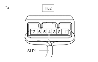
*a Component with harness connected
(Steering Lock ECU (Steering Lock Actuator or Upper Bracket Assembly))Standard Resistance
Tester Connection Condition Specified Condition H52-4 (SLP1) - Body ground Positive (+) tester probe → H52-4 (SLP1)
Negative (-) tester probe → Body groundSteering locked → unlocked* 10 kΩ or higher → Below 1 Ω HINT:
- *: If any of the doors are opened with the shift lever in P and the ignition switch off, the steering will be locked. If the ignition switch is turned to ACC or ON with the electrical key transmitter sub-assembly in the cabin, the steering will be unlocked.
- DTC B2285 may be stored due to a malfunction in the steering lock ECU (steering lock actuator or upper bracket assembly). The steering lock position signal and unlock position signal are sent from the steering lock ECU (steering lock actuator or upper bracket assembly) to the certification ECU (smart key ECU assembly) individually.
Result
Result Proceed to OK (except Toyota Entune Remote Connect Compatible Type) A OK (for Toyota Entune Remote Connect Compatible Type) B NG C
Result:
B
See step 5
Result:
C
REPLACE STEERING LOCK ECU (STEERING LOCK ACTUATOR OR UPPER BRACKET ASSEMBLY). Refer to DISASSEMBLY [12/2019 - 10/2021]
Result:
A
See step 4
- Measure the resistance according to the value(s) in the table below.
- CHECK HARNESS AND CONNECTOR (CERTIFICATION ECU (SMART KEY ECU ASSEMBLY) - STEERING LOCK ECU (STEERING LOCK ACTUATOR OR UPPER BRACKET ASSEMBLY))
- Disconnect the H48 certification ECU (smart key ECU assembly) connector.
- Disconnect the H52 steering lock ECU (steering lock actuator or upper bracket assembly) connector.
- Measure the resistance according to the value(s) in the table below.
Standard Resistance
Tester Connection Condition Specified Condition H48-14 (SLP) - H52-4 (SLP1) Always Below 1 Ω H48-14 (SLP) or H52-4 (SLP1) - Other terminals and body ground Always 10 kΩ or higher Result
Proceed to OK NG
Result:
OK
REPLACE CERTIFICATION ECU (SMART KEY ECU ASSEMBLY). Refer to REMOVAL [12/2019 - 11/2023]
Result:
NG
REPAIR OR REPLACE HARNESS OR CONNECTOR
- CHECK HARNESS AND CONNECTOR (CERTIFICATION ECU (SMART KEY ECU ASSEMBLY) - STEERING LOCK ECU (STEERING LOCK ACTUATOR OR UPPER BRACKET ASSEMBLY) - DCM)
- Disconnect the H48 certification ECU (smart key ECU assembly) connector.
- Disconnect the H52 steering lock ECU (steering lock actuator or upper bracket assembly) connector.
- Disconnect the H11 DCM (telematics transceiver) connector.
- Measure the resistance according to the value(s) in the table below.
Standard Resistance
Tester Connection Condition Specified Condition H48-14 (SLP) - H52-4 (SLP1) Always Below 1 Ω H52-4 (SLP1) - H11-30 (SLPD) Always Below 1 Ω H48-14 (SLP), H52-4 (SLP1) or H11-30 (SLPD) - Other terminals and body ground Always 10 kΩ or higher - Measure the voltage according to the value(s) in the table below.
Standard Voltage
Tester Connection Condition Specified Condition H48-14 (SLP), H52-4 (SLP1) or H11-30 (SLPD) - Body ground Always Below 1 V Result
Proceed to OK NG
Result:
NG
REPAIR OR REPLACE HARNESS OR CONNECTOR
Result:
OK
See step 6
- CHECK CERTIFICATION ECU (SMART KEY ECU ASSEMBLY)
- Check the push-button start function.
- Enter the vehicle while carrying an electrical key transmitter sub-assembly.
- Depress the brake pedal with the shift lever in P.
- Check that the engine starts when the engine switch is pressed.
Result
Result Proceed to Engine starts A Engine does not start B
Result:
A
REPLACE DCM (TELEMATICS TRANSCEIVER). Refer to REMOVAL [12/2019 - 10/2022]
Result:
B
REPLACE CERTIFICATION ECU (SMART KEY ECU ASSEMBLY). Refer to REMOVAL [12/2019 - 11/2023]
- Check the push-button start function.