Power Back Door ECU Communication Stop Mode [11/2023 - ]: Procedure
- CHECK FOR OPEN IN CAN BUS LINES (MULTIPLEX NETWORK DOOR ECU BRANCH LINE)
- Disconnect the cable from the negative (-) battery terminal.
- Disconnect the W30 multiplex network door ECU connector.
- Measure the resistance according to the value(s) in the table below.
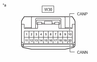
*a Front view of wire harness connector
(to Multiplex Network Door ECU)Standard Resistance
Tester Connection Condition Specified Condition W30-10 (CANP) - W30-20 (CANN) Cable disconnected from negative (-) battery terminal 54 to 69 Ω Result
Proceed to OK NG
Result:
NG
REPAIR OR REPLACE CAN BRANCH LINES OR CONNECTOR (MULTIPLEX NETWORK DOOR ECU)
Result:
OK
See step 2
- CHECK HARNESS AND CONNECTOR (POWER SOURCE CIRCUIT)
- Disconnect the W27 and W28 multiplex network door ECU connectors.
- Measure the resistance according to the value(s) in the table below.
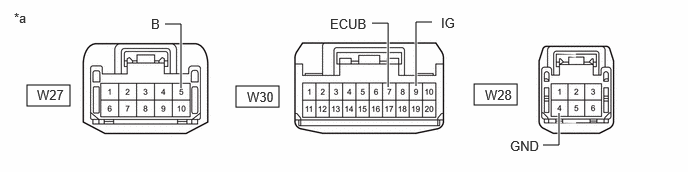
*a Front view of wire harness connector
(to Multiplex Network Door ECU)- - Standard Resistance
Tester Connection Condition Specified Condition W28-4 (GND) - Body ground Cable disconnected from negative (-) battery terminal Below 1 Ω - Reconnect the cable to the negative (-) battery terminal.
- Measure the voltage according to the value(s) in the table below.
Standard Voltage
Tester Connection Condition Specified Condition W27-5 (B) - Body ground Always 11 to 14 V W30-7 (ECUB) - Body ground Always 11 to 14 V W30-9 (IG) - Body ground Ignition switch ON 11 to 14 V Result
Proceed to OK NG
Result:
OK
REPLACE MULTIPLEX NETWORK DOOR ECU
Refer to REMOVAL [11/2023 - ]
Result:
NG
REPAIR OR REPLACE HARNESS OR CONNECTOR (POWER SOURCE CIRCUIT)