Power Source Mode does not Change to ON (READY) [10/2021 - 11/2023]: Procedure
- CHECK POWER SWITCH CONDITION
- Get into the vehicle while carrying an electrical key transmitter sub-assembly.
- Move the shift lever to P.
- With the brake pedal released, check that pressing the power switch causes the power source mode to change.
Result
Result Proceed to Power source mode changes: Off → ACC → ON → off A Power source mode does not change to ACC or ON B Power source mode changes to ON but not to ACC C Power source mode changes to ACC but not to ON D
Result:
B
GO TO OTHER PROBLEM (Power Source Mode does not Change to ON (IG and ACC)). Refer to Power Source Mode does not Change to ON (IG and ACC) [12/2019 - 11/2023]
Result:
C
GO TO OTHER PROBLEM (Power Source Mode does not Change to ON (ACC)). Refer to Power Source Mode does not Change to ON (ACC) [12/2019 - 11/2023]
Result:
D
GO TO OTHER PROBLEM (Power Source Mode does not Change to ON (IG)). Refer to Power Source Mode does not Change to ON (IG) [12/2019 - 11/2023]
Result:
A
See step 2
- READ VALUE USING GTS (STOP LIGHT SWITCH1)
- Read the Data List according to the display on the GTS.
Body Electrical > Power Source Control > Data List
Tester Display Measurement Item Range Normal Condition Diagnostic Note Stop Light Switch1 State of brake pedal OFF or ON OFF: Brake pedal released
ON: Brake pedal depressed- Use this item to determine if the stop light switch assembly is malfunctioning.
- The hybrid control system cannot be started when this item is OFF.
- If the stop light switch assembly is malfunctioning, the hybrid control system can be started by pressing and holding the power switch for a certain period of time.
Body Electrical > Power Source Control > Data List
Tester Display Stop Light Switch1 OK
The GTS display changes correctly in response to the brake pedal operation.
Result
Proceed to OK NG
Result:
NG
See step 7
Result:
OK
See step 3
- Read the Data List according to the display on the GTS.
- READ VALUE USING GTS (SHIFT P SIGNAL)
- Read the Data List according to the display on the GTS.
Body Electrical > Power Source Control > Data List
Tester Display Measurement Item Range Normal Condition Diagnostic Note Shift P Signal Shift position P OFF or ON OFF: Shift lever not in P
ON: Shift lever in PUse this item to determine whether the shift lever position switch (P) is malfunctioning. Body Electrical > Power Source Control > Data List
Tester Display Shift P Signal OK
The GTS display changes correctly in response to the shift lever operation.
Result
Proceed to OK NG
Result:
NG
See step 9
Result:
OK
See step 4
- Read the Data List according to the display on the GTS.
- READ VALUE USING GTS (STARTER REQUEST SIGNAL)
- Read the Data List according to the display on the GTS.
Body Electrical > Power Source Control > Data List
Tester Display Measurement Item Range Normal Condition Diagnostic Note Starter Request Signal Hybrid control system start request signal status OFF or ON OFF: The power switch is not pressed
ON: With the shift lever in P and the brake pedal depressed, the power switch is pressed and held- When the hybrid control system cannot be started due to a start request signal malfunction, OFF is displayed.
- When the power switch is pressed, the duration of time that ON is displayed will be extremely short. As such, the power switch needs to be pressed and held for a certain period of time.
Body Electrical > Power Source Control > Data List
Tester Display Starter Request Signal NOTE:Check that the key indicator display is displayed on the multi-information display in the combination meter assembly, and then press the power switch.
OK
The GTS display changes correctly in response to the power switch operation.
Result
Proceed to OK NG
Result:
NG
See step 10
Result:
OK
See step 5
- Read the Data List according to the display on the GTS.
- CHECK HARNESS AND CONNECTOR (CERTIFICATION ECU (SMART KEY ECU ASSEMBLY) - HYBRID VEHICLE CONTROL ECU)
- Disconnect the H48 certification ECU (smart key ECU assembly) connector.
- Disconnect the H67 hybrid vehicle control ECU connector.
- Measure the resistance according to the value(s) in the table below.
Standard Resistance
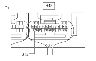
Tester Connection Condition Specified Condition H48-27 (ST2) - H67-4 (ST2) Always Below 1 Ω H48-27 (ST2) or H67-4 (ST2) - Other terminals and body ground Always 10 kΩ or higher Result
Proceed to OK NG
Result:
NG
REPAIR OR REPLACE HARNESS OR CONNECTOR
Result:
OK
See step 6
- CHECK CERTIFICATION ECU (SMART KEY ECU ASSEMBLY)
- Connect the H48 certification ECU (smart key ECU assembly) connector.
- Connect the H67 hybrid vehicle control ECU connector.
- Measure the voltage according to the value(s) in the table below.
Standard Voltage
Tester Connection Condition Specified Condition H48-27 (ST2) - Body ground With the brake pedal depressed, the power switch is pressed and held → After approx. 3 sec. has elapsed, the power switch is released 8.5 V or higher → 1.0 V or less *a Component with harness connected
(Certification ECU (Smart Key ECU Assembly))Result
Proceed to OK NG
Result:
OK
GO TO HYBRID CONTROL SYSTEM
for 2WD: Refer to HOW TO PROCEED WITH TROUBLESHOOTING [12/2019 - 11/2023]
for AWD: Refer to HOW TO PROCEED WITH TROUBLESHOOTING [12/2019 - 11/2023]
Result:
NG
REPLACE CERTIFICATION ECU (SMART KEY ECU ASSEMBLY). Refer to REMOVAL [12/2019 - 11/2023]
- CHECK STOP LIGHT SWITCH ASSEMBLY
- Check the stop light switch assembly.
Refer to ON-VEHICLE INSPECTION [12/2019 - ]
Result
Proceed to OK NG
Result:
NG
REPLACE STOP LIGHT SWITCH ASSEMBLY. Refer to REMOVAL [12/2019 - ]
Result:
OK
See step 8
- Check the stop light switch assembly.
- CHECK HARNESS AND CONNECTOR (CERTIFICATION ECU (SMART KEY ECU ASSEMBLY) - STOP LIGHT SWITCH ASSEMBLY)
- Disconnect the A42 stop light switch assembly connector.
- Disconnect the M5 certification ECU (smart key ECU assembly) connector.
- Disconnect the A31 hybrid vehicle control ECU connector.
- Disconnect the A57 No. 2 skid control ECU (brake actuator assembly) connector.
- Measure the resistance according to the value(s) in the table below.
Standard Resistance
Tester Connection Condition Specified Condition M5-25 (STP1) - A42-3 (L) Always Below 1 Ω M5-25 (STP1) or A42-3 (L) - Other terminals and body ground Always 10 kΩ or higher Result
Proceed to OK NG
Result:
OK
REPLACE CERTIFICATION ECU (SMART KEY ECU ASSEMBLY). Refer to REMOVAL [12/2019 - 11/2023]
Result:
NG
REPAIR OR REPLACE HARNESS OR CONNECTOR
- CHECK SHIFT LOCK CONTROL UNIT ASSEMBLY
- Measure the voltage according to the value(s) in the table below.
Standard Voltage
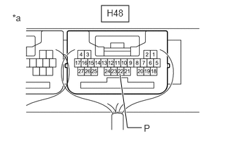
Tester Connection Condition Specified Condition H48-22 (P) - Body ground Shift lever in P → Shift lever not in P 9 V or higher → 2.76 V or less *a Component with harness connected
(Certification ECU (Smart Key ECU Assembly))Result
Proceed to OK NG
Result:
OK
REPLACE CERTIFICATION ECU (SMART KEY ECU ASSEMBLY). Refer to REMOVAL [12/2019 - 11/2023]
Result:
NG
See step 11
- Measure the voltage according to the value(s) in the table below.
- CHECK SECURITY INDICATOR LIGHT (IMMOBILIZER FUNCTION UNSET)
- Get into the vehicle while carrying an electrical key transmitter sub-assembly.
- Move the shift lever to P.
- Press the power switch with the brake pedal released and check that the security indicator light changes from blinking to off at the same time that the power source mode changes to ACC.
OK
The security indicator light changes from blinking to off at the same time that the power source mode changes to ACC.
HINT:
The immobilizer function can be determined to be operating correctly if the security indicator light changes from blinking to off at the same time that the power source mode changes to ACC.
Result
Proceed to OK NG
Result:
OK
REPLACE CERTIFICATION ECU (SMART KEY ECU ASSEMBLY). Refer to REMOVAL [12/2019 - 11/2023]
Result:
NG
GO TO OTHER PROBLEM (Immobilizer System does not Operate Properly). Refer to Immobilizer System does not Operate Properly [12/2019 - 11/2023]
- CHECK HARNESS AND CONNECTOR (CERTIFICATION ECU (SMART KEY ECU ASSEMBLY) - SHIFT LOCK CONTROL UNIT ASSEMBLY)
- Disconnect the H48 certification ECU (smart key ECU assembly) connector.
- Disconnect the H28 shift lock control unit assembly connector.
- Measure the resistance according to the value(s) in the table below.
Standard Resistance
Tester Connection Condition Specified Condition H48-22 (P) - H28-3 (P2) Always Below 1 Ω H48-22 (P) or H28-3 (P2) - Other terminals and body ground Always 10 kΩ or higher Result
Proceed to OK NG
Result:
OK
REPLACE SHIFT LOCK CONTROL UNIT ASSEMBLY. Refer to DISASSEMBLY [12/2019 - ]
Result:
NG
REPAIR OR REPLACE HARNESS OR CONNECTOR