Door Mirror ECU RH Communication Stop Mode [12/2019 - 11/2023]: Procedure
- CHECK FOR OPEN IN CAN BUS LINES (OUTER MIRROR CONTROL ECU ASSEMBLY RH BRANCH LINE)
- Disconnect the cable from the negative (-) battery terminal.
- Disconnect the J7 outer mirror control ECU assembly RH connector.
- Measure the resistance according to the value(s) in the table below.
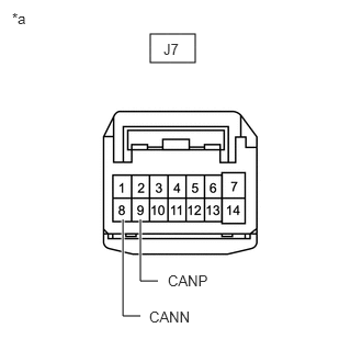
*a Front view of wire harness connector
(to Outer Mirror Control ECU Assembly RH)Standard Resistance
Tester Connection Condition Specified Condition J7-9 (CANP) - J7-8 (CANN) Cable disconnected from negative (-) battery terminal 54 to 69 Ω Result
Result OK NG
Result:
NG
REPAIR OR REPLACE CAN BRANCH LINES OR CONNECTOR (OUTER MIRROR CONTROL ECU ASSEMBLY RH)
Result:
OK
See step 2
- CHECK HARNESS AND CONNECTOR (POWER SOURCE CIRCUIT)
- Measure the resistance according to the value(s) in the table below.
Standard Resistance
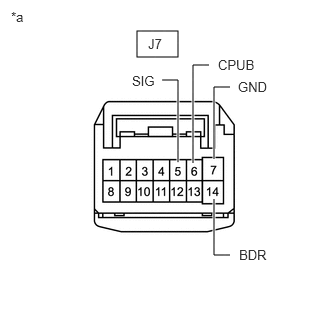
Tester Connection Condition Specified Condition J7-7 (GND) - Body ground Cable disconnected from negative (-) battery terminal Below 1 Ω *a Front view of wire harness connector
(to Outer Mirror Control ECU Assembly RH) - Reconnect the cable to the negative (-) battery terminal.
- Measure the voltage according to the value(s) in the table below.
Standard Voltage
Tester Connection Condition Specified Condition J7-5 (SIG) - Body ground Ignition switch ON 11 to 14 V J7-6 (CPUB) - Body ground Always 11 to 14 V J7-14 (BDR) - Body ground Always 11 to 14 V Result
Result OK NG
Result:
OK
REPLACE OUTER MIRROR CONTROL ECU ASSEMBLY RH
Refer to REMOVAL [12/2019 - ]
Result:
NG
REPAIR OR REPLACE HARNESS OR CONNECTOR (POWER SOURCE CIRCUIT)
- Measure the resistance according to the value(s) in the table below.