DTC P0705-13: Transmission Range Sensor "A" Circuit Open; DTC P0705-62: Transmission Range Sensor "A" Signal Compare Failure [12/2019 - 10/2022]: Procedure
- READ VALUE USING GTS (NEUTRAL POSITION SW AND SHIFT SW STATUS)
- According to the display on the GTS, read the Data List.
Powertrain > Engine > Data List
Tester Display Neutral Position SW Shift SW Status (P Range) Shift SW Status (R Range) Shift SW Status (N Range) Shift SW Status (N, P Range) Shift SW Status (D Range) OK
GTS Display Shift Lever Position Specified Condition Neutral Position SW P or N ON Except P or N OFF Shift SW Status (P Range) P ON Except P OFF Shift SW Status (R Range) R ON Except R OFF Shift SW Status (N Range) N ON Except N OFF Shift SW Status (N, P Range) P or N ON Except P or N OFF Shift SW Status (D Range) D or M ON Except D or M OFF Result
Proceed to OK NG
Result:
NG
See step 6
Result:
OK
See step 2
- According to the display on the GTS, read the Data List.
- READ VALUE USING GTS (SHIFT SW STATUS (S RANGE))
- Read the Data List displayed on the GTS.
Powertrain > Engine > Data List
Tester Display Shift SW Status (S Range) OK
GTS Display Shift Lever Position Specified Condition Shift SW Status (S Range) M ON Except M OFF Result
Proceed to OK NG
Result:
OK
CHECK FOR INTERMITTENT PROBLEMS. Refer to CHECK FOR INTERMITTENT PROBLEMS [12/2019 - 10/2022]
Result:
NG
See step 3
- Read the Data List displayed on the GTS.
- INSPECT SHIFT LOCK CONTROL UNIT ASSEMBLY (TRANSMISSION CONTROL SWITCH)
- for 2WD models: Refer to INSPECTION [12/2019 - 10/2022]
- for AWD models: Refer to INSPECTION [12/2019 - 10/2022]
Result
Proceed to OK NG Result:
NG
REPLACE SHIFT LOCK CONTROL UNIT ASSEMBLY (TRANSMISSION CONTROL SWITCH)
- for 2WD models: Refer to REMOVAL [12/2019 - 10/2022]
- for AWD models: Refer to REMOVAL [12/2019 - 10/2022]
Result:
OK
See step 4
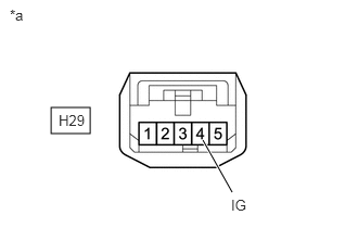
- CHECK TERMINAL VOLTAGE (POWER SOURCE OF TRANSMISSION CONTROL SWITCH)
*a Front view of wire harness connector
(to Transmission Control Switch)- Disconnect the transmission control switch connector.
- Turn the ignition switch to ON.
- Measure the voltage according to the value(s) in the table below.
Standard Voltage
Tester Connection Condition Specified Condition H29-4 (IG) - Body ground Ignition switch ON 11 to 14 V Result
Proceed to OK NG
Result:
NG
REPAIR OR REPLACE HARNESS OR CONNECTOR (TRANSMISSION CONTROL SWITCH POWER SOURCE CIRCUIT)
Result:
OK
See step 5
- CHECK HARNESS AND CONNECTOR (TRANSMISSION CONTROL SWITCH - ECM)
- Disconnect the transmission control switch connector.
- Disconnect the ECM connector.
- Measure the resistance according to the value(s) in the table below.
Standard Resistance
Tester Connection Condition Specified Condition H29-5 (S) - A28-17 (S) Always Below 1 Ω H29-5 (S) or A28-17 (S) - Body ground and other terminals Always 10 kΩ or higher Result
Proceed to OK NG
Result:
OK
REPLACE ECM. Refer to REMOVAL [12/2019 - 09/2020] , or refer to REMOVAL [09/2020 - 10/2022]
Result:
NG
REPAIR OR REPLACE HARNESS OR CONNECTOR
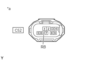
- CHECK TERMINAL VOLTAGE (POWER SOURCE OF PARK/NEUTRAL POSITION SWITCH ASSEMBLY)
*a Front view of wire harness connector
(to Park/Neutral Position Switch Assembly)- Disconnect the park/neutral position switch assembly connector.
- Turn the ignition switch to ON.
- Measure the voltage according to the value(s) in the table below.
Standard Voltage
Tester Connection Condition Specified Condition C52-1 (RB) - Body ground Ignition switch ON 11 to 14 V Result
Proceed to OK NG
Result:
NG
REPAIR OR REPLACE HARNESS OR CONNECTOR (PARK/NEUTRAL POSITION SWITCH ASSEMBLY POWER SOURCE CIRCUIT)
Result:
OK
See step 7
- INSPECT PARK/NEUTRAL POSITION SWITCH ASSEMBLY
- for 2WD models: Refer to INSPECTION [12/2019 - 10/2022]
- for AWD models: Refer to INSPECTION [12/2019 - 10/2022]
Result
Proceed to OK NG Result:
NG
REPLACE PARK/NEUTRAL POSITION SWITCH ASSEMBLY
- for 2WD models: Refer to REMOVAL [12/2019 - 10/2022]
- for AWD models: Refer to REMOVAL [12/2019 - 10/2022]
Result:
OK
See step 8
- CHECK HARNESS AND CONNECTOR (PARK/NEUTRAL POSITION SWITCH ASSEMBLY - ECM)
- Disconnect the park/neutral position switch assembly connector.
- Disconnect the ECM connector.
- Measure the resistance according to the value(s) in the table below.
Standard Resistance
Tester Connection Condition Specified Condition C52-4 (B) - C54-106 (NSW) Always Below 1 Ω C52-7 (DL) - C54-139 (D) Always Below 1 Ω C52-8 (NL) - C54-140 (N) Always Below 1 Ω C52-2 (RL) - C54-107 (R) Always Below 1 Ω C52-3 (PL) - C54-108 (P) Always Below 1 Ω C52-4 (B) or C54-106 (NSW) - Body ground and other terminals Always 10 kΩ or higher C52-7 (DL) or C54-139 (D) - Body ground and other terminals Always 10 kΩ or higher C52-8 (NL) or C54-140 (N) - Body ground and other terminals Always 10 kΩ or higher C52-2 (RL) or C54-107 (R) - Body ground and other terminals Always 10 kΩ or higher C52-3 (PL) or C54-108 (P) - Body ground and other terminals Always 10 kΩ or higher Result
Proceed to OK NG
Result:
OK
REPLACE ECM. Refer to REMOVAL [12/2019 - 09/2020] , or refer to REMOVAL [09/2020 - 10/2022]
Result:
NG
REPAIR OR REPLACE HARNESS OR CONNECTOR