DTC P0365-2A: Camshaft Position Sensor "B" Bank 1 Signal Stuck in Range; DTC P0365-31: Camshaft Position Sensor "B" Bank 1 No Signal; DTC P0390-31: Camshaft Position Sensor "B" Bank 2 No Signal [12/2019 - 10/2022]: Procedure
- CHECK HARNESS AND CONNECTOR
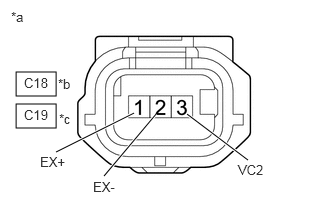
*a Front view of wire harness connector
(to VVT Sensor (for Exhaust Camshaft))*b Bank 1 *c Bank 2 HINT:
Make sure that the connector is properly connected. If it is not, securely connect it and check for DTCs again.
- Disconnect the VVT sensor (for exhaust camshaft) connector.
- Turn the ignition switch to ON.
- Measure the voltage according to the value(s) in the table below.
Standard Voltage
Tester Connection Condition Specified Condition C18-3 (VC2) - Body ground Ignition switch ON 4.5 to 5.5 V C19-3 (VC2) - Body ground Ignition switch ON 4.5 to 5.5 V C18-1 (EX+) - Body ground Ignition switch ON 3.0 to 5.0 V C19-1 (EX+) - Body ground Ignition switch ON 3.0 to 5.0 V - Turn the ignition switch off and wait for at least 30 seconds.
- Measure the resistance according to the value(s) in the table below.
Standard Resistance
Tester Connection Condition Specified Condition C18-3 (VC2) - C18-1 (EX+) Ignition switch off 1.425 to 1.575 kΩ C19-3 (VC2) - C19-1 (EX+) Ignition switch off 1.425 to 1.575 kΩ C18-2 (EX-) - Body ground Always Below 1 Ω C19-2 (EX-) - Body ground Always Below 1 Ω Result
Proceed to OK NG
Result:
NG
See step 4
Result:
OK
See step 2
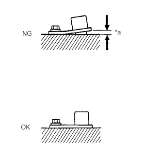
- CHECK SENSOR INSTALLATION AND CONDUCT VISUAL INSPECTION (VVT SENSOR (FOR EXHAUST CAMSHAFT))
*a Clearance - Visually check the VVT sensor (for exhaust camshaft) for damage.
- Check the VVT sensor (for exhaust camshaft) installation condition.
OK
The VVT sensor (for exhaust camshaft) does not have any damage and is installed properly.
Result
Proceed to OK NG
Result:
NG
SECURELY REINSTALL VVT SENSOR (FOR EXHAUST CAMSHAFT)
Refer to INSTALLATION [12/2019 - 10/2022]
Result:
OK
See step 3
- INSPECT EXHAUST CAMSHAFT (TIMING ROTOR)
- Check the timing rotor of the exhaust camshaft.
OK
Camshaft timing rotor does not have any cracks or deformation.
HINT:
Perform "Inspection After Repair" after replacing the exhaust camshaft.
Refer to INITIALIZATION [12/2019 - 10/2022]
Result
Proceed to OK NG
Result:
OK
REPLACE VVT SENSOR (FOR EXHAUST CAMSHAFT)
Refer to REMOVAL [12/2019 - 10/2022]
Result:
NG
REPLACE EXHAUST CAMSHAFT
Refer to REMOVAL [12/2019 - 10/2022]
- Check the timing rotor of the exhaust camshaft.
- CHECK HARNESS AND CONNECTOR (VVT SENSOR (FOR EXHAUST CAMSHAFT) - ECM)
- Disconnect the VVT sensor (for exhaust camshaft) connector.
- Disconnect the ECM connector.
- Measure the resistance according to the value(s) in the table below.
Standard Resistance
Tester Connection Condition Specified Condition C18-1 (EX+) - C54-131 (EV1+) Always Below 1 Ω C18-2 (EX-) - C54-100 (VV1-) Always Below 1 Ω C18-3 (VC2) - C54-99 (VCV1) Always Below 1 Ω C19-1 (EX+) - C54-130 (EV2+) Always Below 1 Ω C19-2 (EX-) - C54-97 (VV2-) Always Below 1 Ω C19-3 (VC2) - C54-98 (VCV2) Always Below 1 Ω C18-1 (EX+) or C54-131 (EV1+) - Body ground and other terminals Always 10 kΩ or higher C18-2 (EX-) or C54-100 (VV1-) - Body ground and other terminals Always 10 kΩ or higher C18-3 (VC2) or C54-99 (VCV1) - Body ground and other terminals Always 10 kΩ or higher C19-1 (EX+) or C54-130 (EV2+) - Body ground and other terminals Always 10 kΩ or higher C19-2 (EX-) or C54-97 (VV2-) - Body ground and other terminals Always 10 kΩ or higher C19-3 (VC2) or C54-98 (VCV2) - Body ground and other terminals Always 10 kΩ or higher Result
Proceed to OK NG
Result:
OK
REPLACE ECM
Refer to REMOVAL [12/2019 - 09/2020] , or refer to REMOVAL [09/2020 - 10/2022]
Result:
NG
REPAIR OR REPLACE HARNESS OR CONNECTOR