Caution / Notice / Hint
HINT:
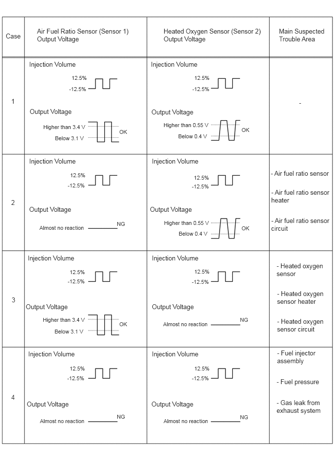
Malfunctioning areas can be identified by performing the Control the Injection Volume for A/F Sensor function provided in the Active Test. The Control the Injection Volume for A/F Sensor function can help to determine whether the air fuel ratio sensor, heated oxygen sensor and other potential trouble areas are malfunctioning.
The following instructions describe how to conduct the Control the Injection Volume for A/F Sensor operation using the GTS.
- Connect the GTS to the DLC3.
- Start the engine.
- Turn the GTS on.
- Warm up the engine and run the engine at an engine speed of 2500 rpm for approximately 90 seconds.
- Enter the following menus: Powertrain / Engine / Active Test / Control the Injection Volume for A/F Sensor / Data List / A/F (O2) Sensor Voltage B1S1 and O2 Sensor Voltage B1S2 or A/F (O2) Sensor Voltage B2S1 and O2 Sensor Voltage B2S2.
- Perform the Active Test with the engine idling (change the fuel injection volume).
- Monitor the output voltages of the air fuel ratio and heated oxygen sensors (A/F (O2) Sensor Voltage B1S1 and O2 Sensor Voltage B1S2 or A/F (O2) Sensor Voltage B2S1 and O2 Sensor Voltage B2S2) displayed on the GTS.
HINT:
- The Control the Injection Volume for A/F Sensor operation lowers the fuel injection volume by 12.5% or increases the injection volume by 12.5%.
- Each sensor reacts in accordance with increases and decreases in the fuel injection volume.
| GTS Display (Sensor) | Injection Volume | Status | Voltage |
|---|---|---|---|
| A/F (O2) Sensor Voltage B1S1 A/F (O2) Sensor Voltage B2S1 (Air fuel ratio) |
12.5% | Rich | Below 3.1 V |
| -12.5% | Lean | Higher than 3.4 V | |
| O2 Sensor Voltage B1S2 O2 Sensor Voltage B2S2 (Heated oxygen) |
12.5% | Rich | Higher than 0.55 V |
| -12.5% | Lean | Below 0.4 V |
The air fuel ratio sensor has an output delay of a few seconds and the heated oxygen sensor has a maximum output delay of approximately 20 seconds.
- Following the Control the Injection Volume for A/F Sensor procedure enables technicians to check and graph the voltage outputs of both the air fuel ratio and heated oxygen sensors.
- To display the graph, enter the following menus: Powertrain / Engine / Active Test / Control the Injection Volume for A/F Sensor / Data List / A/F (O2) Sensor Voltage B1S1 and O2 Sensor Voltage B1S2 or A/F (O2) Sensor Voltage B2S1 and O2 Sensor Voltage B2S2; and then press the graph button on the Data List view.
Inspect the fuses for circuits related to this system before performing the following procedure.
HINT:
- Bank 1 refers to the bank that includes the No. 1 cylinder*.
*: The No. 1 cylinder is the cylinder which is farthest from the transaxle.
- Bank 2 refers to the bank that does not include the No. 1 cylinder.
- Sensor 1 refers to the sensor closest to the engine assembly.
- Sensor 2 refers to the sensor farthest away from the engine assembly.
- Read Freeze Frame Data using the GTS. The ECM records vehicle and driving condition information as Freeze Frame Data the moment a DTC is stored. When troubleshooting, Freeze Frame Data can help determine if the vehicle was moving or stationary, if the engine was warmed up or not, if the air fuel ratio was lean or rich, and other data from the time the malfunction occurred.