DTC P0136-11: O2 Sensor Circuit Bank 1 Sensor 2 Circuit Short to Ground; DTC P0136-13: O2 Sensor Circuit Bank 1 Sensor 2 Circuit Open; DTC P0136-14: O2 Sensor Circuit Bank 1 Sensor 2 Circuit Short to Ground or Open; DTC P0136-15: O2 Sensor Circuit Bank 1 Sensor 2 Circuit Short to Battery or Open; DTC P0136-17: O2 Sensor Circuit Bank 1 Sensor 2 Circuit Voltage Above Threshold; DTC P0136-1C: O2 Sensor Circuit Bank 1 Sensor 2 Circuit Voltage Out of Range; DTC P0136-23: O2 Sensor Circuit Bank 1 Sensor 2 Signal Stuck Low; DTC P013A-00: O2 Sensor Slow Response - Rich to Lean Bank 1 Sensor 2; DTC P013C-00: O2 Sensor Slow Response - Rich to Lean Bank 2 Sensor 2; DTC P0156-11: O2 Sensor Circuit Bank 2 Sensor 2 Circuit Short to Ground; DTC P0156-13: O2 Sensor Circuit Bank 2 Sensor 2 Circuit Open; DTC P0156-14: O2 Sensor Circuit Bank 2 Sensor 2 Circuit Short to Ground or Open; DTC P0156-15: O2 Sensor Circuit Bank 2 Sensor 2 Circuit Short to Battery or Open; DTC P0156-17: O2 Sensor Circuit Bank 2 Sensor 2 Circuit Voltage Above Threshold; DTC P0156-1C: O2 Sensor Circuit Bank 2 Sensor 2 Circuit Voltage Out of Range; DTC P0156-23: O2 Sensor Circuit Bank 2 Sensor 2 Signal Stuck Low [12/2019 - 10/2022]: Procedure
- READ OUTPUT DTC
- Read the DTCs.
Powertrain > Engine > Trouble Codes
Result
Result Proceed to P0136-1C or P0156-1C is output A DTC P0136-15 or P0156-15 is output B DTC P0136-14, P0136-17, P0156-14 or P0156-17 is output C DTC P0136-11, P0136-13, P0156-11 or P0156-13 is output D DTC P0136-23, P013A-00, P013C-00 or P0156-23 is output E DTC P0136-11, P0136-13, P0136-14, P0136-15, P0136-17, P0136-1C, P0136-23, P013A-00, P013C-00, P0156-11, P0156-13, P0156-14, P0156-15, P0156-17, P0156-1C or P0156-23 and other DTCs are output F HINT:
If any DTCs other than P0136-11, P0136-13, P0136-14, P0136-15, P0136-17, P0136-1C, P0136-23, P013A-00, P013C-00, P0156-11, P0156-13, P0156-14, P0156-15, P0156-17, P0156-1C or P0156-23 are output, troubleshoot those DTCs first.
Result:
B
See step 5
Result:
C
See step 12
Result:
D
See step 7
Result:
E
See step 18
Result:
F
GO TO DTC CHART. Refer to DIAGNOSTIC TROUBLE CODE CHART [12/2019 - 09/2020] , or refer to DIAGNOSTIC TROUBLE CODE CHART [09/2020 - 10/2021] , or refer to DIAGNOSTIC TROUBLE CODE CHART [10/2021 - 10/2022]
Result:
A
See step 2
- Read the DTCs.
- READ VALUE USING GTS (O2 SENSOR VOLTAGE)
- Start the engine.
- Allow the engine to idle.
- Read the heated oxygen sensor output voltage while idling.
Powertrain > Engine > Data List
Tester Display O2 Sensor Voltage B1S2 O2 Sensor Voltage B2S2 Result
Heated Oxygen Sensor Output Voltage Proceed to 1.0 V or higher A Less than 1.0 V B
Result:
A
See step 5
Result:
B
See step 3
- PERFORM ACTIVE TEST USING GTS (CONTROL THE INJECTION VOLUME FOR A/F SENSOR)
- Start the engine and warm it up until the engine coolant temperature reaches 75°C (167°F) or higher.
Powertrain > Engine > Data List
Tester Display Coolant Temperature - Change the fuel injection volume using the GTS, and monitor the voltage output of air fuel ratio sensor (A/F (O2) Sensor Voltage B1S1, A/F (O2) Sensor Voltage B2S1) and heated oxygen sensor (O2 Sensor Voltage B1S2, O2 Sensor Voltage B2S2) displayed on the GTS.
Powertrain > Engine > Active Test
Active Test Display Control the Injection Volume for A/F Sensor Data List Display A/F (O2) Sensor Voltage B1S1 A/F (O2) Sensor Voltage B2S1 O2 Sensor Voltage B1S2 O2 Sensor Voltage B2S2 HINT:
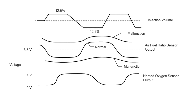
- The Active Test "Control the Injection Volume for A/F Sensor" can be used to lower the fuel injection volume by 12.5% or increases the injection volume by 12.5%.
- The air fuel ratio sensor is displayed as A/F (O2) Sensor Voltage B1S1 or A/F (O2) Sensor Voltage B2S1, and the heated oxygen sensor is displayed as O2 Sensor Voltage B1S2 or O2 Sensor Voltage B2S2 on the GTS.
- The air fuel ratio sensor has an output delay of a few seconds and the heated oxygen sensor has a maximum output delay of approximately 20 seconds.
- If the sensor output voltage does not change (almost no reaction) while performing the Active Test, the sensor may be malfunctioning.
Result
GTS Display (Sensor) Voltage Variation Proceed to A/F (O2) Sensor Voltage B1S1 or A/F (O2) Sensor Voltage B2S1 (Air fuel ratio) Alternates between higher and less than 3.3 V OK Remains at higher than 3.3 V NG Remains at less than 3.3 V HINT:
A normal heated oxygen sensor voltage (O2 Sensor Voltage B1S2 or O2 Sensor Voltage B2S2) reacts in accordance with increases and decreases in fuel injection volumes. When the air fuel ratio sensor voltage (A/F (O2) Sensor Voltage B1S1 or A/F (O2) Sensor Voltage B2S1) remains at either less or higher than 3.3 V despite the heated oxygen sensor indicating a normal reaction, the air fuel ratio sensor is malfunctioning.
Result:
NG
See step 9
Result:
OK
See step 4
- Start the engine and warm it up until the engine coolant temperature reaches 75°C (167°F) or higher.
- INSPECT AIR FUEL RATIO SENSOR
HINT:
This air fuel ratio sensor test is to check the air fuel ratio sensor current during the fuel-cut operation. When the sensor is normal, the sensor current will indicate below 2.2 mA in this test.
- Clear the DTCs.
Powertrain > Engine > Clear DTCs
- Start the engine and warm it up until the engine coolant temperature reaches 75°C (167°F) or higher.
Powertrain > Engine > Data List
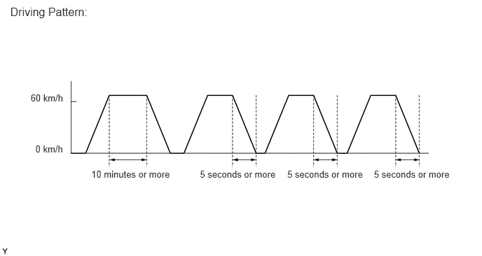
Tester Display Coolant Temperature - Drive the vehicle at 60 km/h (37 mph) or more for 10 minutes or more.WARNING:
When performing the confirmation driving pattern, obey all speed limits and traffic laws.
- Stop the vehicle.
- Read the value of the air fuel ratio sensor current while the fuel-cut operation is performed.
Powertrain > Engine > Data List
Tester Display Vehicle Speed A/F (O2) Sensor Current B1S1 A/F (O2) Sensor Current B2S1 - Drive the vehicle at 60 km/h (37 mph) or more and release the accelerator pedal for at least 5 seconds without depressing the brake pedal in order to execute fuel-cut control. Perform this 3 times.WARNING:
When performing the confirmation driving pattern, obey all speed limits and traffic laws.
Standard Current
Less than 2.2 mA
HINT:
- To measure the air fuel ratio sensor current precisely, perform the fuel-cut operation as long as possible.
- If it is difficult to measure the air fuel ratio sensor current, use the snapshot function of the GTS.
Result
Proceed to OK NG
Result:
OK
See step 15
Result:
NG
See step 9
- Clear the DTCs.
- INSPECT HEATED OXYGEN SENSOR (CHECK FOR SHORT)
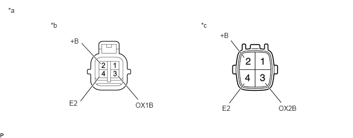
*a Component without harness connected
(Heated Oxygen Sensor)*b Bank 1 *c Bank 2 - - - Disconnect the heated oxygen sensor connector.
- Measure the resistance according to the value(s) in the table below.
Standard Resistance
Tester Connection Condition Specified Condition 2 (+B) - 4 (E2) Always 10 kΩ or higher 2 (+B) - 3 (OX1B) Always 10 kΩ or higher 2 (+B) - 4 (E2) Always 10 kΩ or higher 2 (+B) - 3 (OX2B) Always 10 kΩ or higher HINT:
Perform "Inspection After Repair" after replacing the heated oxygen sensor.
Refer to INITIALIZATION [12/2019 - 10/2022]
Result
Proceed to OK NG
Result:
NG
REPLACE HEATED OXYGEN SENSOR. Refer to REMOVAL [12/2019 - 10/2022]
Result:
OK
See step 6
- CHECK HARNESS AND CONNECTOR (CHECK FOR SHORT)
- Turn the ignition switch off and wait for 5 minutes or more.
- Disconnect the ECM connector.
- Measure the resistance according to the value(s) in the table below.
Standard Resistance
Tester Connection Condition Specified Condition C54-50 (HT1B) - C54-93 (OX1B) Always 10 kΩ or higher C54-16 (HT2B) - C54-91 (OX2B) Always 10 kΩ or higher Result
Proceed to OK NG
Result:
OK
REPLACE ECM. Refer to REMOVAL [12/2019 - 09/2020] , or refer to REMOVAL [09/2020 - 10/2022]
Result:
NG
REPAIR OR REPLACE HARNESS OR CONNECTOR (HEATED OXYGEN SENSOR - ECM)
- PERFORM ACTIVE TEST USING GTS (CONTROL THE INJECTION VOLUME FOR A/F SENSOR)
- Start the engine and warm it up until the engine coolant temperature reaches 75°C (167°F) or higher.
Powertrain > Engine > Data List
Tester Display Coolant Temperature - Change the fuel injection volume using the GTS, and monitor the voltage output of heated oxygen sensor displayed on the GTS.
Powertrain > Engine > Active Test
Active Test Display Control the Injection Volume for A/F Sensor Data List Display O2 Sensor Voltage B1S2 O2 Sensor Voltage B2S2 HINT:
- The Control the Injection Volume for A/F Sensor operation lowers the fuel injection volume by 12.5% or increases the injection volume by 12.5%.
- The heated oxygen sensor has a maximum output delay of approximately 20 seconds.
Standard voltage
Fluctuates between 0.4 V or less, and 0.55 V or higher.
Result
Proceed to OK NG
Result:
NG
See step 12
Result:
OK
See step 8
- Start the engine and warm it up until the engine coolant temperature reaches 75°C (167°F) or higher.
- PERFORM ACTIVE TEST USING GTS (CONTROL THE INJECTION VOLUME FOR A/F SENSOR)
- Start the engine and warm it up until the engine coolant temperature reaches 75°C (167°F) or higher.
Powertrain > Engine > Data List
Tester Display Coolant Temperature - Change the fuel injection volume using the GTS, and monitor the voltage output of air fuel ratio sensor (A/F (O2) Sensor Voltage B1S1, A/F (O2) Sensor Voltage B2S1) and heated oxygen sensor (O2 Sensor Voltage B1S2, O2 Sensor Voltage B2S2) displayed on the GTS.
Powertrain > Engine > Active Test
Active Test Display Control the Injection Volume for A/F Sensor Data List Display A/F (O2) Sensor Voltage B1S1 A/F (O2) Sensor Voltage B2S1 O2 Sensor Voltage B1S2 O2 Sensor Voltage B2S2 HINT:
- The Control the Injection Volume for A/F Sensor operation lowers the fuel injection volume by 12.5% or increases the injection volume by 12.5%.
- The air fuel ratio sensor is displayed as A/F (O2) Sensor Voltage B1S1 or A/F (O2) Sensor Voltage B2S1, and the heated oxygen sensor is displayed as O2 Sensor Voltage B1S2 or O2 Sensor Voltage B2S2 on the GTS.
- The air fuel ratio sensor has an output delay of a few seconds and the heated oxygen sensor has a maximum output delay of approximately 20 seconds.
- If the sensor output voltage does not change (almost no reaction) while performing the Active Test, the sensor may be malfunctioning.
Result
GTS Display (Sensor) Voltage Variation Proceed to A/F (O2) Sensor Voltage B1S1 or A/F (O2) Sensor Voltage B2S1 (Air fuel ratio) Alternates between higher and less than 3.3 V OK Remains at higher than 3.3 V NG Remains at less than 3.3 V HINT:
A normal heated oxygen sensor voltage (O2 Sensor Voltage B1S2 or O2 Sensor Voltage B2S2) reacts in accordance with increases and decreases in fuel injection volumes. When the air fuel ratio sensor voltage (A/F (O2) Sensor Voltage B1S1 or A/F (O2) Sensor Voltage B2S1) remains at either less or higher than 3.3 V despite the heated oxygen sensor indicating a normal reaction, the air fuel ratio sensor is malfunctioning.
Result:
OK
CHECK ENGINE TO DETERMINE CAUSE OF EXTREMELY RICH OR LEAN ACTUAL AIR FUEL RATIO (FUEL INJECTOR ASSEMBLY, FUEL SYSTEM, INTAKE SYSTEM, ETC.). Refer to DTC P0171-00: System Too Lean Bank 1; DTC P0172-00: System Too Rich Bank 1; DTC P0174-00: System Too Lean Bank 2; DTC P0175-00: System Too Rich Bank 2; DTC P1170-00: Fuel Performance/Port Injector; DTC P117B-00: Fuel Performance/Direct Injector [12/2019 - 10/2022]
Result:
NG
See step 9
- Start the engine and warm it up until the engine coolant temperature reaches 75°C (167°F) or higher.
- REPLACE AIR FUEL RATIO SENSOR
Refer to REMOVAL [12/2019 - 10/2022]
HINT:
Perform "Inspection After Repair" after replacing the air fuel ratio sensor.
Refer to INITIALIZATION [12/2019 - 10/2022]
Result
Proceed to NEXT Result:
NEXT
See step 10
- CLEAR DTC
- Clear the DTCs.
Powertrain > Engine > Clear DTCs
- Turn the ignition switch off and wait for at least 30 seconds.
Result
Proceed to NEXT
Result:
NEXT
See step 11
- Clear the DTCs.
- CHECK WHETHER DTC OUTPUT RECURS (DTC P0136-11, P0136-13, P0136-1C, P0156-11, P0156-13 OR P0156-1C)
- Drive the vehicle in accordance with the driving pattern described in Confirmation Driving Pattern.
- Check that the DTC monitor is NORMAL. If the DTC monitor is INCOMPLETE, perform the drive pattern again but increase the vehicle speed.
Powertrain > Engine > Utility
Tester Display All Readiness - Input the DTC: P0136-11, P0136-13, P0136-1C, P0156-11, P0156-13 or P0156-1C.
Result
Result Proceed to NORMAL
(DTCs are not output)A ABNORMAL
(DTC P0136-11, P0136-13, P0136-1C, P0156-11, P0156-13 or P0156-1C is output)B HINT:
Perform "Inspection After Repair" after replacing the heated oxygen sensor.
Refer to INITIALIZATION [12/2019 - 10/2022]
Result:
A
END
Result:
B
REPLACE HEATED OXYGEN SENSOR. Refer to REMOVAL [12/2019 - 10/2022]
- CHECK FOR EXHAUST GAS LEAK
- Check for exhaust gas leaks.
OK
No gas leaks in exhaust system.
HINT:
Perform "Inspection After Repair" after repairing or replacing the exhaust system.
Refer to INITIALIZATION [12/2019 - 10/2022]
Result
Proceed to OK NG
Result:
NG
REPAIR OR REPLACE EXHAUST GAS LEAK POINT
Result:
OK
See step 13
- Check for exhaust gas leaks.
- INSPECT HEATED OXYGEN SENSOR (HEATER RESISTANCE)
Refer to INSPECTION [12/2019 - 10/2022]
HINT:
Perform "Inspection After Repair" after replacing the heated oxygen sensor.
Refer to INITIALIZATION [12/2019 - 10/2022]
Result
Proceed to OK NG Result:
NG
REPLACE HEATED OXYGEN SENSOR. Refer to REMOVAL [12/2019 - 10/2022]
Result:
OK
See step 14
- CHECK HARNESS AND CONNECTOR (HEATED OXYGEN SENSOR - ECM)
- Disconnect the heated oxygen sensor connector.
- Disconnect the ECM connector.
- Measure the resistance according to the value(s) in the table below.
Standard Resistance
Tester Connection Condition Specified Condition C49-1 (HT1B) - C54-50 (HT1B) Always Below 1 Ω C49-3 (OX1B) - C54-93 (OX1B) Always Below 1 Ω C49-4 (E2) - C54-94 (EX1B) Always Below 1 Ω C50-1 (HT2B) - C54-16 (HT2B) Always Below 1 Ω C50-3 (OX2B) - C54-91 (OX2B) Always Below 1 Ω C50-4 (E2) - C54-92 (EX2B) Always Below 1 Ω C49-1 (HT1B) or C54-50 (HT1B) - Body ground and other terminals Always 10 kΩ or higher C49-3 (OX1B) or C54-93 (OX1B) - Body ground and other terminals Always 10 kΩ or higher C50-1 (HT2B) or C54-16 (HT2B) - Body ground and other terminals Always 10 kΩ or higher C50-3 (OX2B) or C54-91 (OX2B) - Body ground and other terminals Always 10 kΩ or higher Result
Proceed to OK NG
Result:
NG
REPAIR OR REPLACE HARNESS OR CONNECTOR
Result:
OK
See step 15
- REPLACE HEATED OXYGEN SENSOR
Refer to REMOVAL [12/2019 - 10/2022]
HINT:
Perform "Inspection After Repair" after replacing the heated oxygen sensor.
Refer to INITIALIZATION [12/2019 - 10/2022]
Result
Proceed to NEXT Result:
NEXT
See step 16
- CLEAR DTC
- Clear the DTCs.
Powertrain > Engine > Clear DTCs
- Turn the ignition switch off and wait for at least 30 seconds.
Result
Proceed to NEXT
Result:
NEXT
See step 17
- Clear the DTCs.
- CHECK WHETHER DTC OUTPUT RECURS (DTC P0136-11, P0136-13, P0136-14, P0136-17, P0136-1C, P0156-11, P0156-13, P0156-14, P0156-17 OR P0156-1C)
- Drive the vehicle in accordance with the driving pattern described in Confirmation Driving Pattern.
- Check that the DTC monitor is NORMAL. If the DTC monitor is INCOMPLETE, perform the drive pattern again but increase the vehicle speed.
Powertrain > Engine > Utility
Tester Display All Readiness - Input the DTC: P0136-11, P0136-13, P0136-14, P0136-17, P0136-1C, P0156-11, P0156-13, P0156-14, P0156-17 or P0156-1C.
Result
Result Proceed to NORMAL
(DTCs are not output)A ABNORMAL
(DTC P0136-11, P0136-13, P0136-14, P0136-17, P0136-1C, P0156-11, P0156-13, P0156-14, P0156-17 or P0156-1C is output)B HINT:
Perform "Inspection After Repair" after replacing the air fuel ratio sensor.
Refer to INITIALIZATION [12/2019 - 10/2022]
Result:
A
END
Result:
B
REPLACE AIR FUEL RATIO SENSOR. Refer to REMOVAL [12/2019 - 10/2022]
- CHECK FOR EXHAUST GAS LEAK
- Check for exhaust gas leaks.
OK
No gas leaks in exhaust system.
HINT:
Perform "Inspection After Repair" after repairing or replacing the exhaust system.
Refer to INITIALIZATION [12/2019 - 10/2022]
Result
Proceed to OK NG
Result:
NG
REPAIR OR REPLACE EXHAUST GAS LEAK POINT
Result:
OK
See step 19
- Check for exhaust gas leaks.
- CHECK HARNESS AND CONNECTOR (CHECK FOR SHORT)
- Turn the ignition switch off and wait for 5 minutes or more.
- Disconnect the ECM connector.
- Measure the resistance according to the value(s) in the table below.
Standard Resistance
Tester Connection Condition Specified Condition C54-50 (HT1B) - C54-93 (OX1B) Always 10 kΩ or higher C54-16 (HT2B) - C54-91 (OX2B) Always 10 kΩ or higher Result
Proceed to OK NG
Result:
NG
REPAIR OR REPLACE HARNESS OR CONNECTOR (HEATED OXYGEN SENSOR - ECM)
Result:
OK
See step 20
- CLEAR DTC
- Clear the DTCs.
Powertrain > Engine > Clear DTCs
- Turn the ignition switch off and wait for at least 30 seconds.
Result
Proceed to NEXT
Result:
NEXT
See step 21
- Clear the DTCs.
- READ OUTPUT DTC (DTC P0136-23, P013A-00, P013C-00 OR P0156-23 IS OUTPUT AGAIN)
- Drive the vehicle in accordance with the driving pattern described in Confirmation Driving Pattern.
- Check that the DTC monitor is NORMAL. If the DTC monitor is INCOMPLETE, perform the drive pattern again but increase the vehicle speed.
Powertrain > Engine > Utility
Tester Display All Readiness - Input the DTC: P0136-23, P013A-00, P013C-00 or P0156-23.
Result
Result Proceed to NORMAL
(DTCs are not output)A ABNORMAL
(DTC P0136-23, P013A-00, P013C-00 or P0156-23 is output)B HINT:
Perform "Inspection After Repair" after replacing the heated oxygen sensor.
Refer to INITIALIZATION [12/2019 - 10/2022]
Result:
A
CHECK FOR INTERMITTENT PROBLEMS. Refer to CHECK FOR INTERMITTENT PROBLEMS [12/2019 - 10/2022]
Result:
B
REPLACE HEATED OXYGEN SENSOR. Refer to REMOVAL [12/2019 - 10/2022]